EBB 2240/2209 CAN

For information about EBB SB2240/2209 CAN V1.0 structure, please click :
Product Profile
BIGTREETECH EBB SB2240/2209 CAN V1.0 is a tool board for the 3D printing team of Shenzhen BIQU Innovation Technology Co., Ltd. to adapt VoronStealthBurner. It can communicate via USB or CAN, greatly simplifying wiring。
Features Highlights
- BOOT and RESET keys are reserved on the main board. Users can enter DFU mode through USB to update firmware.
- The protection circuit of the on-board thermistor to prevent the main control chip from burning due to the leakage of the heating rod.
- The thermistor can select the pull-up resistance value through the jumper, which supports PT1000 (2.2K pull-up resistance) and is convenient for customers to use DIY.
- On-board proximity switch interface, which can connect proximity switch conveniently and quickly, and support the selection of proximity switch NPN/PNP type.
- Onboard 2-way CNC fan, 1-way 4-wire fan interface.
- On-board 3-way limit switch, 1-way BLTOUCH interface.
- USB power-on is selected through jumper cap to effectively isolate DC-DC and USB5V of the main board.
- Proximity switch, CNC fan, 4-wire fan support VIN/12V/5V voltage selection
- On-board SPI output interface. This port is reserved with 2 independent IO ports, which can be used for material breaking and blocking detection, or DIY operation of other functions.
- The anti-flyback diode is added at the heating rod and fan port to effectively protect the MOS tube from being burnt by the reverse voltage.
- The power interface has anti-reverse connection protection to prevent the board from burning when the customer connects the reverse power line during DIY.
- On-board MAX31865, supporting 2-wire/4-wire PT100/PT1000 selection.
- Support CAN or USB communication, wherein the terminal resistance 120R of CAN can be selected through the jumper cap, and the CAN expansion interface is reserved.
- The USB port is equipped with ESD protection chip to prevent the master controller from being broken down by the static electricity of the USB port
- The factory is equipped with terminals, female springs, two-way studs and screws required by DIY, which greatly meets the customer's DIY requirements.
- Used with BIGTREETECH EBB SB0000 CAN V1.0, perfectly compatible with VoronStealthBurner structure.
Specifications
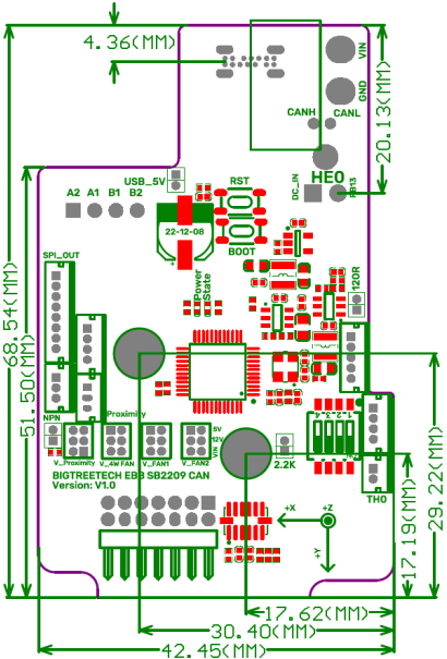
| Appearance dimension | 68.5mm*42.5mm. For further details please read: Dimensions |
|---|---|
| MCU | Arm® 32-bit Cortex®-M0+ CPU STM32G0B1CBT6 64MHz |
| Input Voltage | DC12V-DC24V 9A |
| Logic Voltage | DC 3.3V |
| Heating interface | Heating rod (E0), maximum output current: 5A |
| On-board sensor | ADXL345 |
| Fan connector | Two numerical control fans (FAN0, FAN1). One 4-wire fan interface. |
| Maximum output current of fan interface | 1A, peak 1.5A |
| Expand interface | EndStop, ABL, RGB, PT100/PT1000, USB interface, CAN interface, SPI interface |
| Motor Drive | Onboard TMC2240/TMC2209 |
| Drive operating mode | TMC2240(SPI)/TMC2209(UART) |
| Stepper motor interface | EM |
| Temperature sensor interface | 1-way 100K NTC or PT1000 (TH0), 1-way PT100/PT1000 optional |
| USB communication interface | USB-Type-C |
| DCDC 5V output maximum current | 1A |
Note: BTT EBB SB2240/2209 CAN V1.0only supports Klipper at the present.
Dimensions
Version:EBB SB2240 V1.0

Version:EBB SB2209 V1.0
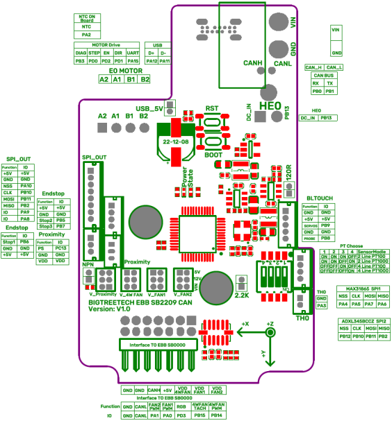
Pinout
Version:EBB SB2240 V1.0
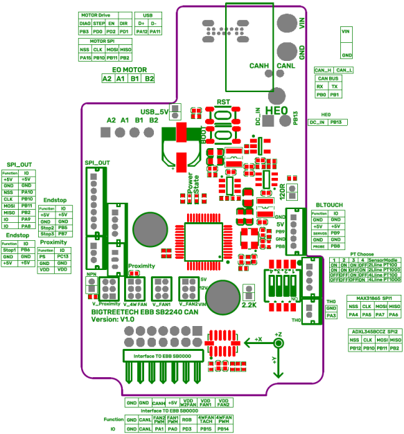
Version:EBB SB2209 V1.0
Hardware Configuration
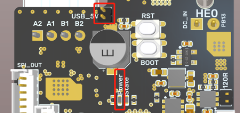
USB Power Supply
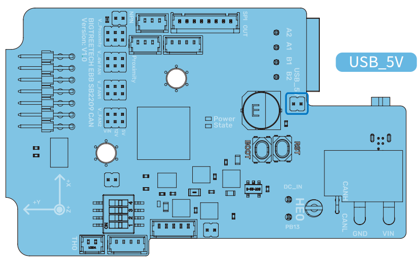
After the main board is powered on, the Power red light will light up, indicating that the power supply is normal. The VUSB in the middle of the board is the power selection end. Only when USB is used to power the main board, it is necessary to use the jump cap to short connect the VUSB. Main board does not support external power supply through TYPE C.
Download firmware using DFU
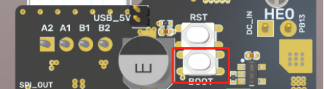
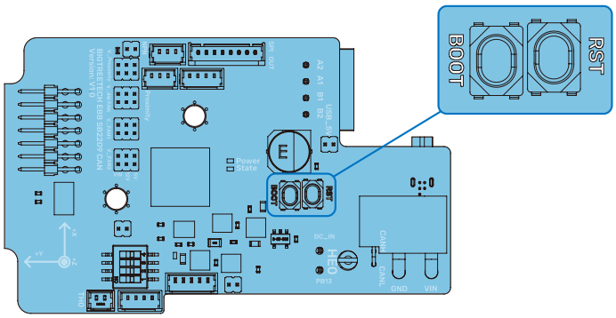
Press and hold the on-board BOOT key to power on the main board, or press the BOOT key and then press the RST key. The chip enters DFU mode. At this time, you can connect TYPE C to the PC and program the main control chip through DFU mode.
Hardware Installation
Heating Rod Connection
The heating rod is connected to the main board through the on-board 5569 2PIN connector, supporting the maximum continuous 5A current output

100K NTC or PT1000 Settings
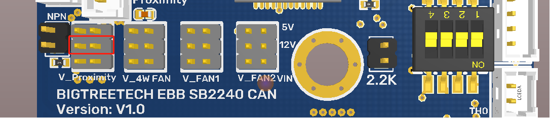
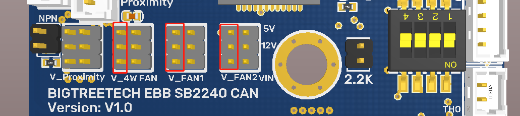
1.When using 100K NTC thermistor, it is not necessary to insert the jumper cap. At this time, the pull-up resistance of TH0 is 4.7K. When using PT1000, it is necessary to use the two pins in the red box below the jump cap. At this time, the pull-up resistance of TH0 is 2.2K
Note: BTT EEB42 CAN V1.0/V1.1 only supports Klipper at the present.
2.Use MAX31865: select PT100/PT1000, two or four wires through dial switch
| 1 | 2 | 3 | 4 | Sensor Model |
| 0N | 0N | 0N | OFF | Two Lines PT100 |
| 0N | 0N | OFF | OFF | Two Lines PT1000 |
| OFF | OFF | 0N | OFF | Four Lines PT100 |
| OFF | OFF | OFF | 0N | Four Lines PT1000 |
PT100/PT1000 2-wire connection diagram PT100/PT1000 4-wire connection diagram

BLTouch Wiring

Proximity Switch Connection
1.The wiring diagram of proximity switch is shown as follows

2.Wiring switch voltage selection
The user can select different voltage (VIN/12V/5V) to supply power to the proximity switch through the jumper cap.

3.Use+5V to power the proximity switch
Use the jump cap to short circuit the horizontal row of 5V voltage selected by the fan voltage.
4.Use 12V to power the proximity switch
Use the jump cap to short circuit the horizontal pin of the 12V voltage selected by the fan voltage.

Note: It is forbidden to short circuit the voltage of the proximity switch to select any two rows of pins on the right side of the row pin, and only one circuit of power supply voltage is allowed to supply power to the proximity switch at any time. Otherwise, the motherboard will be damaged (as shown below).

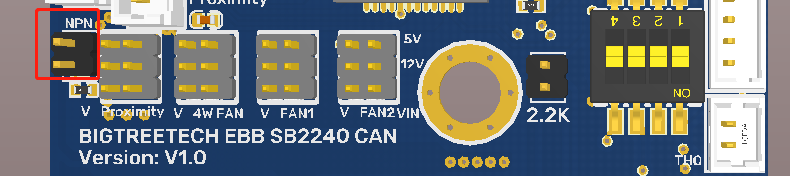
5.Proximity switch type selection
The design of the motherboard proximity switch interface supports PNP and NPN proximity switches, which is convenient for users to connect different types of proximity switches to the motherboard. The default connection type is PNP. If NPN type is needed, just use the jumper cap to short the NPN pin on the motherboard.
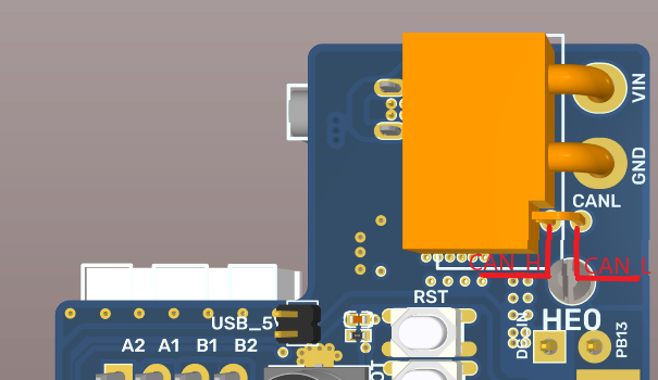
CAN BUS Connection
The motherboard has two built-in CAN BUS interfaces, one is located at the power input interface and the other is located at the BIGTREETECH EBB SB0000 CAN board.

Fan Voltage Selection
BIGTREETECH EBB SB2240/2209 CAN has built-in 2-way NC fan and 1-way 4-wire fan. Each fan can select different voltage (VIN/12V/5V) through jumper cap to adapt to fans with different working voltage.
Use+5V to power the fan
Use the jump cap to short circuit the horizontal row of 5V voltage selected by the fan voltage

Use+12V to power the fan
Use the jump cap to short circuit the horizontal row of 12V voltage selected by the fan voltage

Use input voltage to power the fan
Use the jump cap to short the horizontal pin of the VIN voltage selected by the fan voltage

Note: It is forbidden to short circuit the fan voltage to select any two rows of pins on the left side of the row pin, and only one circuit of power supply voltage is allowed to supply power to the fan at any time. Otherwise, the motherboard will be damaged (as shown below)
CAN connection with BIGTREETECH EBB SB0000

Note: Pay attention to the installation direction of the main board. Incorrect installation direction will cause irreversible damage to the main board.
RGB Wiring

RGB connection port is located on BIGTREETECH EBB SB0000 CAN board
NC fan Interface
On-board 2-way numerical control fan interface, through the BIGTREETECH EBB SB0000 CAN board FAN1, FAN2 is connected to the fan to realize the controllable connection of the fan.

Linear fan Connection
One 4-wire fan interface on the board can be connected to the 4-wire fan through the 4-wire fan interface on the BIGTREETECH EBB SB0000 CAN board.

Note: The rated working voltage of the fan used must be consistent with the voltage selected by the fan to prevent the fan from working abnormally or being damaged due to the mismatched working voltage.
Software Configuration
FLASHING KATAPULT
Note: "Katapult" is the New Name for "CanBoot"
Please note that Katapult is designed for the purpose of directly updating the MCU firmware via the CAN bus interface. If you prefer the DFU update method, you may skip this step
“Flashing Katapult on a CB1/Raspberry Pi”
Refer to the instructions here to download the Katapult project : https://github.com/Arksine/Katapult
1、 Runcd~ to enter the home directory, then run:
to download Katapult project.
run:
to enter the Katapult directory.
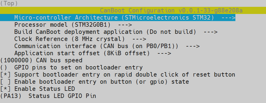
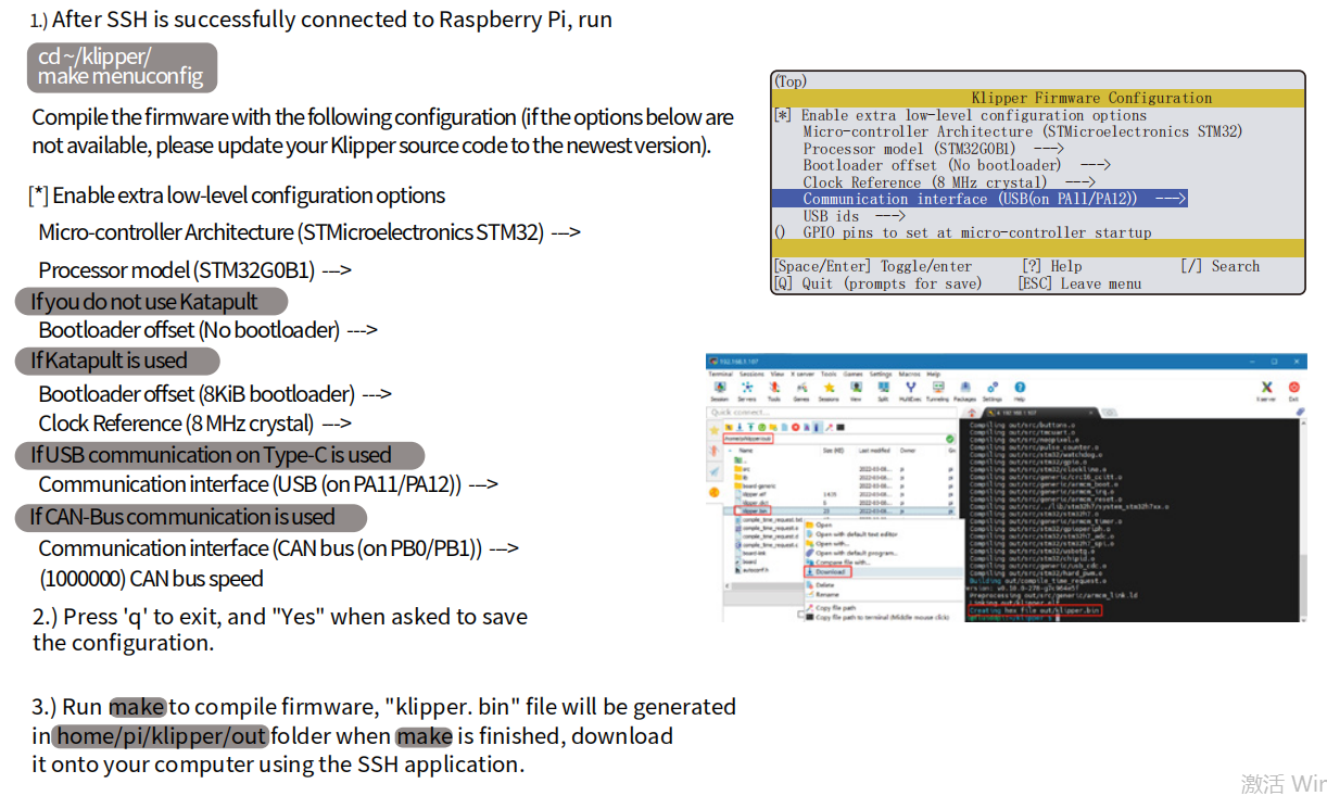
2、 Enter make menuconfig and configure according to the following figure
3、 Runmake to compile firmware, 'katapult.bin' file will be generated in home/biqu/Katapult/out folder when make is finished, download it onto your computer using the SSH application.

4、 Please use a Type-C cable to connect the EBB SB2240/2209 CAN to the Raspberry Pi/CB1, and ensure that the USB_5V jumper is connected, in order to supply power to the EBB SB2240/2209 CAN via Type-C.
5、 Press and hold the Boot button, and then click the Reset button to enter the DFU mode.
6、 Enter in the SSH terminal command line
Query DFU device ID
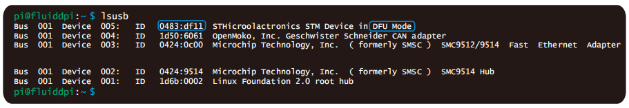
7、 Please enter the following command to flash Katapult:
where "0483:df11" should be replaced with the actual device ID obtained in step 3.5.
8、 After flashing is complete, remove the USB_5V jumper and the Type-C cable.
COMPILE FIRMWARE
FIRMWARE UPDATE(VIA KATAPULT)
1、 To use the CAN bus, you need to connect the CAN bus cable and insert a jumper at the position of the 120R termination resistor.
2、 Run:
then run:

3、 Run:
The be69315a613c is replaced with the actual UUID. Note: klipper.bin needs to be made in advance, and the application start offset of Katapult is 8KiB offset, so Klipper's menuconfig Bootloader offset should also be 8KiB bootloader, as shown in the following figure.

4、 Run:
to query. At this time, the Application changes from Katapult to Klipper, indicating that Klipper has been running normally

FIRMWARE UPDATE(VIA DFU)
Raspberry Pi or CB1 update via DFU.
1、Please use a Type-C cable to connect the EBB SB2240/2209 CAN to the Raspberry Pi/CB1, and ensure that the USB_5V jumper is connected, in order to supply power to theEBB SB2240/2209 CAN via Type-C.
2、Press and hold the Boot button, and then click the Reset button to enter the DFU mode.
3、Enter in the SSH terminal command line
Query DFU device ID
4、Run:
to enter to the klipper directory, then run the following command to write the firmware:
Note: Replace 0483: df11 with the actual device ID found in the previous step.
5、The prompt File downloaded successfully indicates that the writing is completed.
After the writing is completed, there will be an error message: dfu-util: Error during download get_status, just ignore it.
FIRMWARE UPDATE(VIA DFU)
1、After the firmware is written, run
to query the serial ID of the device (this ID can only be found in the USB communication mode, and this step is ignored in CANBus mode).
2、 If USB communication is used, after the first writing, it is not necessary to manually press the Boot and Reset buttons to enter the DFU mode when updating again.
You can directly enter
to write the firmware (Note: replace/dev/serial/by id/xxx with the actual ID found in the previous step).
The prompt File downloaded successfully indicates that the writing is completed. After the writing is completed, there will be an error message: dfu-util: Error during download get_status, just ignore it.
After flashing is complete, remove the USB_5V jumper and the Type-C cable.
CANBus Configuration
For details, please click:
https://bigtreetech.github.io/docs/EBB%20Series.html#canbus-configuration
PRECAUTIONS
- When the TH0 interface does not use PT1000, the jumper cap cannot be inserted above, otherwise the 100K NTC cannot be used normally
- When using CAN communication, you need to see whether it is used as a terminal. If it is a terminal, you must plug the jumper cap on the 120R position;
- When pressing the DIY wire, pay attention to the wire sequence, and carry out the DIY according to the Pin diagram to avoid the power line being connected reversely or missing from the CAN signal, resulting in the module burning;
- When burning the program through the USB port, if there is no external power supply, it is necessary to use the jumper cap to short connect the VUSB to provide the working voltage for the module;
- The load current of the heating rod and fan interface shall not be greater than the maximum withstand current to prevent the MOS tube from burning.
FAQ
Q: Maximum current of heating rod and fan port.
Answer: Maximum output current of heating rod port: 5 A.
Maximum output current of fan interface: 1A, peak 1.5A.
The total current of heating rod+drive+fan should be less than 9A.
Q: USB interface failed to update firmware.
Answer: Make sure that the VUSB jumper cap is inserted and the power indicator on the motherboard is on normally.
Product Purchase Link
Purchase Link:
EBB SB2209 CAN: https://biqu.equipment/products/bigtreetech-ebb-sb2209-can-v1-0?_pos=1&_sid=7000fe7f6&_ss=r&variant=40214282731618
EBB SB2240 CAN: https://biqu.equipment/products/bigtreetech-ebb-sb2209-can-v1-0?variant=40214283485282
If you have any issues with the product, please submit a support ticket.
https://biqu3d.com/pages/submit-a-ticket
Navigation:
BIQU Official Website: http://biqu3d.com
BIGTREETECH Official Website: http://bigtree-tech.com
Online Store: https://biqu.equipment
BIGTREETECH Official Group: https://www.facebook.com/groups/bigtreetech
Discord: https://discord.gg/hhZsV7zk