SKR PRO V1.2
Product Profile
Aiming at some problems existing in 3D printed motherboards in the market. Shenzhen BIQU Innovation Technology Co., Ltd. launched a high performance 3D printer master board with STM32F407ZGT6 as the core controller, BIGTREETECH-SKR-PRO-V1.2.
Features Highlights
- The main control uses the ARM-level Cortex-M4 series with a 32-bit dominant frequency of 168 MHz STM32F407ZGT6 chip, performance is greatly improved;
- Equipped with highly modular open source firmware Marlin2.0, it is convenient for users to DIY and further-development, to avoid the worry of not being able to master the core code;
- Visual Studio Code is a powerful development tool for Marlin2.0. Its integrated development environment has the following advantages: it supports online debugging, which is more helpful for product development and performance optimization, and uses C language for development, which is easy to get started.
- The PCB board layout is rigorous and beautiful, and it is specially designed for heat dissipation.
- Using a dedicated power chip, support 12-24V power input, output current 3A.
- With 24V input and the same power, the hot bed current can be reduced to 1/4, effectively solving the heating problem of hot bed MOS tube.
- BIGTREETECH-2.8-inchTFT, and BIGTREETECH-3.5-inchTFT color touch screens are compatible, as are LCD2004 and LCD12864 screens.
- The system supports Chinese simplified Chinese, English and other languages, which can be switched by itself.
- The firmware is upgraded by SD card, which is simple, convenient and efficient.
- Support Serial WIFI Online Printing.
- 6 motor drives, 3 extruders, 3 CNC fans.
- It has the following functions: data can be saved when power is cut off, materials can be discovered when broken, and works can be turned off when finished.
- High performance MOSFET tube, better heat dissipation effect.
- Using removable fuse to make the replacement process easier.
- Reserve extended ports of BL Touch, PWM, ADC, UART, I2C and SPI.
- Use the power supply option to separate the USB power supply from the switching power supply, which can effectively prevent the computer USB port from being burnt due to a short circuit.
- The special function interface uses a color-conspicuous row pin to greatly reduce the error rate of the wiring.
- As many as 20 expansion ports can be reserved, and extended ports can be used to add more features to the printer without worrying about the shortage of motherboard ports.
- Support offline printing and online printing.
- Support for dual Z axis printers (series dual Z).
Specifications
| Appearance size | 147*95mm |
|---|---|
| Installation size | 138 * 86.5 mm |
| Microprocessor | ARM 32-bit Cortex / M4 CPU |
| Input voltage | DC12V-DC24V |
| Motor driver support | TMC5160,TMC2208,TMC2130,ST820,LV8729, DRV8825,A4988, etc. |
| Driving mode support | TMC2130SPI, TMC5160SPI, TMC2208 UART |
| Motor drive interface | X, Y, Z, E0, E1, E2,total 6 channels. |
| Temperature sensor interface | T0, T1, T2, T3 total 4 channels 100K NTC .(thermal resistance) |
| Display screen | BIGTREETECH- 2.8 inch TFT,BIGTREETECH-3.5 inch TFT, LCD2004,LCD12864 |
| PC communication interface | square USB, convenient to plug and unplug, communication baud rate is 11520 |
| Support Expansion Port | Automatic Shutdown Module After Printing , Power Off Resume Print Module , Filament break detection and Automatic leveling,BL Touch, WIFI, PWM, ADC, UART, I2C and SPI,etc. |
| Support file format | g-code |
| Support machine structure | XYZ, delta, kossel, Ultimaker, corexy |
| Recommended software | Cura, Simplify3D, pronterface, Repetier-host, Makerware |
| multiple power supply, sharing the pressure of single |
Dimensions

Content of the upgrade
- Change the hot bed interface screen printing;
- Change the position of the hot bed fuse, effectively deal with the overheating of the PCB at the bottom of the fuse when the hot bed is heated;
- Analog quantity (AD) input increased clamping diode, effectively protect the chip;
Peripheral Interface
Interface Diagram
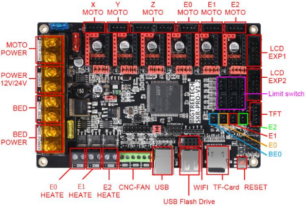
Pin Description

Interface Introduction
mainboard power selection
Power jumper cap selection
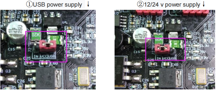
- As shown in the red box, when the jumper cap is connected to IN and VCC, the motherboard selects 12V/24V power supply; when the jumper cap is connected to USB and VCC, the motherboard selects USB power supply.
- If the jumper cap has USB power selected, the 5V and 3.3V indicators will also light.
- When the main board is powered by 12V/24V, the 12V indicator will be lit. If the jumper cap has 12V/24V power supply, the 3.3V, 5V and 12V indicators will be illuminated.
mainboard power wiring methods
- Three Power supply method of switching Power supply

As shown above, three sets of power lines need to be connected to the motherboard, namely, motor power supply, hot bed power supply and motherboard power supply, and the extra group is hot bed interface.
When connecting, be sure to disconnect the 220V power supply and distinguish the positive and negative electrodes so as not to burn out the motherboard.
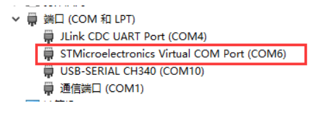
Communication between motherboard and computer
After the motherboard is connected to the computer through the USB cable, the computer will automatically install the driver. In this case,the motherboard can be identified for data transmission. If the installation fails, we can go to our open source Web site:
https://github.com/bigtreetech?tab=repositories to find the corresponding motherboard download driver.
After the drive installation is completed, open the Device Manager to see the port as shown in the figure below, which indicates that the system board is properly connected to the computer.
Description of patterns and interfaces
1、STEP/DIR mode
According to the driver used, the subdivision table is corresponding and the jumper cap is used for subdivision selection.
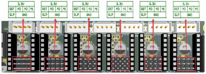
Note: the high level is connected to the above two row needles, and the low level is connected to the following two rows of needles.
2、A4988 and 8825 driver instructions
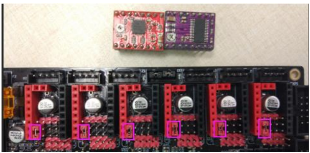
If the drive is using A4988 or 8825, it is necessary to short the two pins in the purple box with the jumper cap (as shown). If it is not A4988 or 8825, the jumper cap in the box needs to be pulled out.
3、UART mode
When using UART mode, you need to short the needle in the red box with a jumper cap.

As shown in the figure below, the Pin foot corresponding to the TMC2208 UART mode is the Pin foot selected by the red box, that is, the 4th Pin pin from the top to the bottom.
4、SPI mode

When using SPI mode, you need to short the needle in the red box with a jumper cap
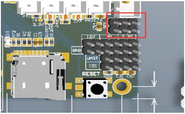
5、USB and U disk selection
As shown in the picture, when the jumper cap is connected to the left, the USB function is turned on while the USB flash drive function is turned off; when the jumper cap is connected to the right, the USB flash drive function is turned on, and the USB function is turned off.
Note: at present, the firmware does not support the USB disk function for the time being.

6、SPI expansion port
The SPI expansion port shares IO with the SPI mode of the driver and can only be used if the SPI mode driver is not used.
7、WIFI interface

The WIFI interface is as shown in the picture above. When the WIFI is inserted, the edge of the board shown by the purple box on the right side faces outward and is inserted vertically.
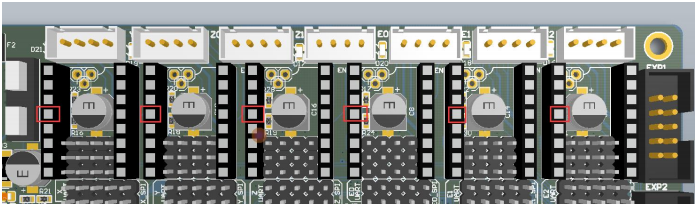
8、stallguard pin description
As shown in the picture below, the purple box is the stall pin corresponding to the stall detection.

Take the TMC2209 as an example. When the stallguard function is not used, the stallguard pin of the TMC2209 needs to be cut off so that the mechanical switch can work normally.
The operation method is as shown below:
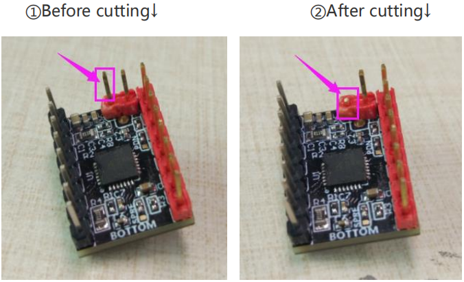
This function pin needs to be trimmed only when the stallguard function is not used.
9、Double Z-axis connection description

10、Description of the indicator light for the limit switch
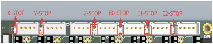
The status indicator is the normally closed limit switch indicator.
First: The indicator light is always on when the limit switch is not connected
Second: When the normally closed limit switch is connected,the indicator light is off, and when it is triggered, the indicator light is illuminated.
Third: When the normally open limit switch is connected, the indicator light is always on, and when it is triggered, the indicator light is off.
motherboard firmware description
1、Currently only supports our open source Marlin2.0 firmware, please go to our open source website:
https://github.com/bigtreetech?tab=repositories
Find the corresponding motherboard to download.
2、Marlin2.0 firmware update method:After downloading our open source Marlin2.0 firmware, use Visual Studio Code to open the project for compilation, then find the firmware.bin file, copy it to the SD card, and then reset the motherboard for about 10 seconds. (You can also download firmware.bin directly)
For detailed steps, please refer to the tutorial:
https://www.dropbox.com/s/ppjfflhf3j5yzh2/MarlinV2.0%20SKRV1.1%20instruction.docx?dl=0
Precausions
- Currently, only our company's open source firmware Marlin2.0 is supported.
- U-disk functionality is not supported for the time being.so stay tuned!
- The power of the hot bed connected to the motherboard must be less than or equal to 180W ( the thermal bed resistance value is greater than 0.8)
- when the motherboard is supplied with 12V/24V power supply, be sure to pay attention to the positive and negative poles of the power supply.
- The firmware file name in the SD card cannot be changed, including capitalization.
- Ensure that all wires, jumper caps and drivers are correctly plugged in before power-on.
- Do not plug or unplug the drive module with power to avoid damage.
- When wiring the motherboard, be sure to pay attention to the positive and negative power supply, drive direction, power supply selection, etc., in order to power on.