MMB CAN V1.0
Product Profile
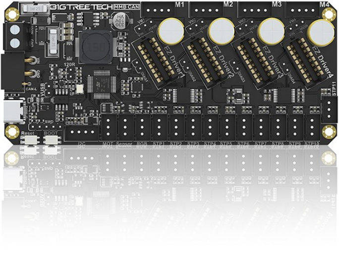
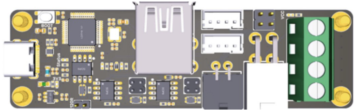
BIGTREETECH MMB CAN V1.0 is a control board for multi-material 3D printing system, e.g., ERCF. It simplifies wiring by communicating via USB or CAN.
Features Highlights
- The board has BOOT and RESET buttons, allowing users to update firmware in DFU mode via USB.
- I2C interface reserved for filament run out/clogging detection, or other DIY functions.
- The power interface has reverse polarity protection to prevent the board from being damaged if power cables are connected incorrectly during DIY.
- Supports CAN or USB communication, with selectable 120R terminal resistance for CAN and reserved CAN expansion interface.
- USB port has ESD protection to prevent controller damage from electrostatic discharge.
- Uses XT30 interface for CAN communication and board power supply, simplifying wiring.
- Stepper motor driver supports high and low voltage selection for DIY use.
Specifications
| Dimensions | 125mm x 54mm |
|---|---|
| Installation size | Refer to BIGTREETECH MMB CAN V1.0-SIZE.pdf |
| Microprocessor | ARM Cortex-M0+ STM32G0B1CBT6 64MHz |
| Input Voltage | DC12V-DC24V 9A |
| Logic Voltage | DC 3.3V |
| Servo Interface (MOT) Maximum Output | 5V 2A, peak 2.5A |
| Expansion Interfaces | STP1-STP11, I2C, RGB, Sensor (infrared sensor interface), USB, CAN |
| Motor Driver Support | EZ Drive (supports voltage selection) |
| Driver Operating Modes | STEP/DIR, UART, SPI |
| Stepper Motor Interfaces | M1, M2, M3, M4 |
| USB Communication Interface | USB Type-C |
| DCDC 5V Output Maximum Current | 3.6A |
Firmware Support
Currently, MMB CAN V1.0 only supports Klipper firmware.
Dimensions

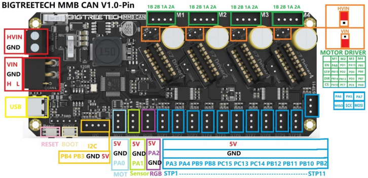
Peripheral Interface
Pin Description
Interface Introduction
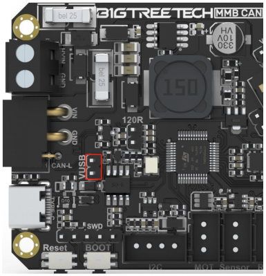
USB Power Supply
After the board is powered on, the power indicator light will turn on, indicating that the power supply is normal. The VUSB label on the board is the power selection terminal, and a jumper is needed to short VUSB only when using USB to power the board.
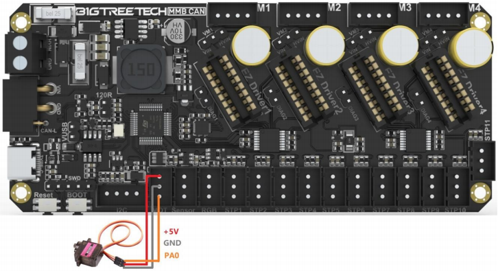
Servo Wiring
RGB-WS2812 Wiring

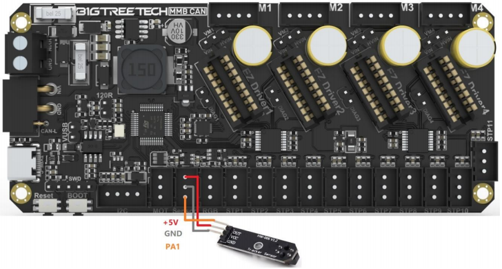
Sensor (e.g., CRT5000 infrared sensor) Wiring
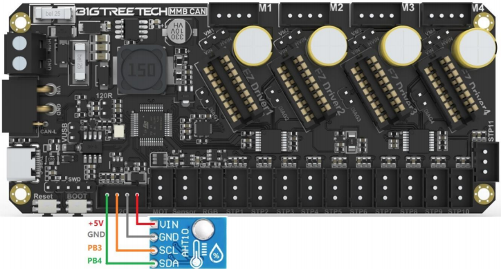
I2C (e.g., AHT10 temperature and humidity sensor) Wiring
Endstop (e.g., Hall sensor) Wiring

Klipper Firmware
Flashing CANBOOT
Note: CanBoot is for updating MCU firmware directly via CAN bus. If you prefer DFU, skip this step.
To flash CanBoot on Raspberry Pi or CB1, follow the instructions at https://github.com/Arksine/CanBoot
-
Enter
cd ~
Navigate to the main directory and input
git clone **https://github.com/Arksine/CanBoot**
to download the CanBoot project. Then enter
cd CanBoot
navigate to the CanBoot directory.
-
Enter
make menuconfig
configure as shown in the provided image:
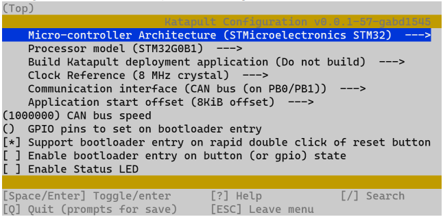
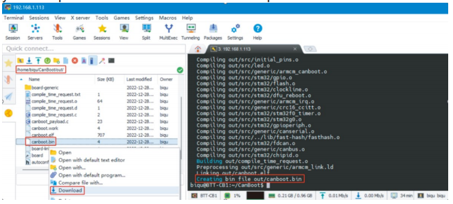
3.Enter make to compile the firmware. The resulting canboot.bin file will be in the home/biqu/CanBoot/out folder. This can be directly downloaded to your computer from the SSH software's left panel.
4.Hold the Boot button and connect the board to Raspberry Pi/CB1 via Type-C cable to enter DFU mode.
5.Enter lsusb in the SSH terminal to query the DFU device ID.
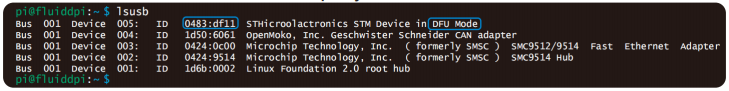
6.Enter the following command to flash CanBoot
make flash FLASH_DEVICE=0483:df11
replacing 0483:df11 with the actual device ID found in the previous step.
7.After flashing, disconnect the Type-C cable.
Compiling Klipper Firmware
1.Connect to CB1/Raspberry Pi via SSH and enter the following
commands:
cd ~/klipper/
make menuconfig
Configure the firmware as shown in the provided image (update Klipper
firmware to the latest version if options are not available).
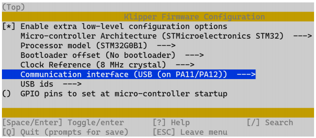
[*] Enable extra low-level configuration optionsMicro-controller
Micro-controller Architecture (STMicroelectronics STM32) --->
Processor model (STM32G0B1) --->
If not using CanBoot
Bootloader offset (No bootloader) --->
If CanBoot is used
Bootloader offset (8KiB bootloader) --->
If USB communication on Type-C is used
Communication interface (USB (on PA11/PA12)) --->
If CAN-Bus communication is used
Communication interface (CAN bus (on PB0/PB1)) --->
(1000000) CAN bus speed
2.After configuration, press q to exit, and select Yes when prompted to save.
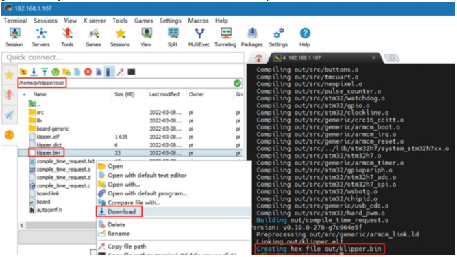
3.Enter make to compile the firmware. The resulting klipper.bin file will be in the home/pi/klipper/out folder. This can be directly downloaded to your computer from the SSH software's left panel.
Firmware Update via CANBOOT
-
Connect the CAN bus cable and plug a jumper at the 120R terminal resistor.
-
Enter
cd ~/CanBoot/scripts
then enter
python3 flash_can.py -i can0 -q
query the canbus ID (make sure the CAN cable is connected and powered on) as shown in the figure below, the UUID of the device has been found:

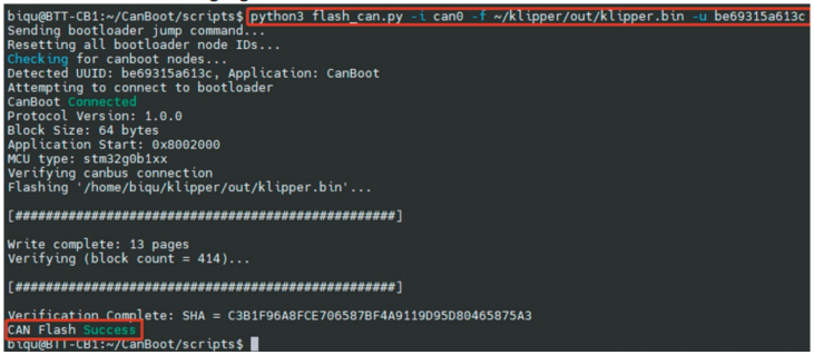
3.Enter
python3 flash_can.py -i can0 -f ~/klipper/out/klipper.bin -u be69315a613c
The be69315a613c is replaced with the actual UUID. Note: klipper.binneeds to be generated in advance using the make command, and the application start offset of CanBoot is 8KiB offset, so Klipper's menuconfig Bootloader offset should also be 8KiB bootloader, as shown in the following figure.
4.Query again with
python3 flash_can.py -i can0 -q
The Application should now show Klipper, indicating it is running correctly.

Firmware Update via DFU
Raspberry Pi or CB1 update via DFU.
1、Hold the Boot button and connect the board to Raspberry Pi/CB1 via Type-C cable to enter DFU mode.
2、Enter lsusb in the SSH terminal to query the DFU device ID.

3、Enter
cd klipper
navigate to the Klipper directory, and enter
make flash FLASH_DEVICE=0483:df11
start flashing the firmware (Note: Replace 0483: df11 with the actual device ID found in the previous step.)
4、After flashing, enter
ls /dev/serial/by-id/
to query the device's Serial ID (only applicable for USB communication, not for CANBus).
5、For USB communication, you don't need to press the Boot button for
subsequent updates. Enter the following command to flash the firmware
make flash FLASH_DEVICE=/dev/serial/by-id/usb-Klipper_stm32g0b1xx_4550357128922FC8-if00
(Note: replacing /dev/serial/by-id/xxx with the actual ID found in the previous step).
6、For CAN bus communication, disconnect the Type-C cable after flashing.
CAN bus Configuration
Use with BIGTREETECH U2C module.
1、Enter the following command in the SSH terminal:
sudo nano /etc/network/interfaces.d/can0
Add the following content:
allow-hotplug can0
iface can0 can static
bitrate 1000000
up ifconfig $IFACE txqueuelen 1024
Set the CAN bus speed to 1M (must match the firmware setting of 1000000 CAN bus speed). Save (Ctrl + S) and exit (Ctrl + X), then enter sudo reboot to restart Raspberry Pi.
2、Each device on CAN bus will generate a canbus_uuid according to the UID of MCU, to find each microcontroller device ID, ensure the hardware is powered on and connected correctly, then run:
~/klippy-env/bin/python ~/klipper/scripts/canbus_query.py can0
3、If an uninitialized CAN device is detected, the command will report the canbus_uuid:
Found canbus_uuid=0e0d81e4210c
4、If Klipper is running and connected to the device, the canbus_uuid will not be reported, which is normal.
Configuring Klipper
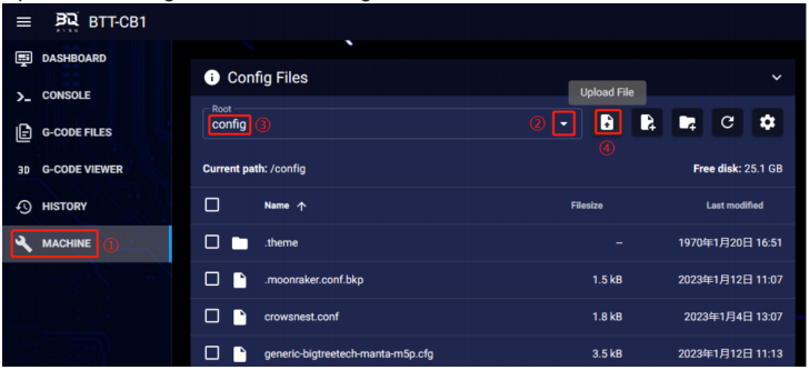
1、In your computer's web browser, enter the Raspberry Pi's IP address, and as shown in the path below, download the reference configuration file sample-bigtreetech-mmb-canbus.cfg. If the file is not available, update Klipper firmware to the latest version or download from:
https://github.com/bigtreetech/MMB

2、Upload the configuration file to Configuration Files.
3、Add the board configuration to the "printer.cfg" file:[include sample-bigtreetech-mmb-canbus.cfg]
4、Modify the ID number in the configuration file to match the actual ID of the board (USB serial or canbus).
5、Configure the module's specific functions according to the instructions at https://www.klipper3d.org/Overview.html