Hermit Crab 2 Series
Product Profile
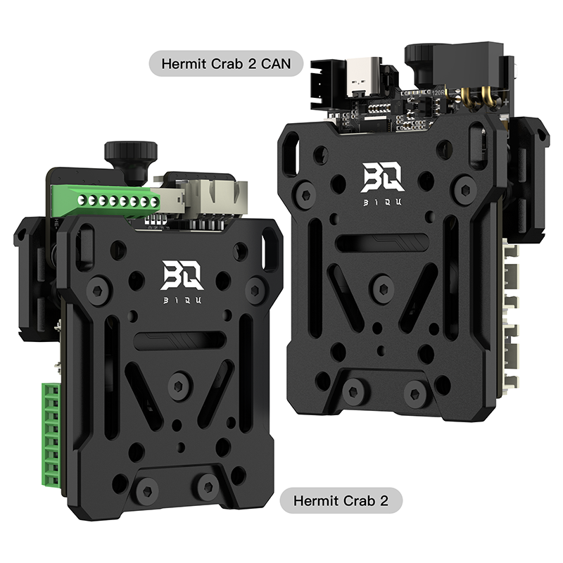
The Hermit Crab 2 series is made for fast and simple swapping of print heads on 3D printers. It has a fixed plate and multiple tool plates that let you quickly change between different print heads. The 2 series is lighter, more compact, and more robust.
Feature Highlights(Hermit Crab 2 CAN)
- The board contains a ‘BOOT’ button to enter DFU mode when updating firmware using USB.
- The thermistor circuit has added protection to prevent the MCU from burning out due to heater cartridge leakage.
- Interfaces such as I2C and RGB are provided for DIY capabilities.
- Fan voltage is compatible with various fan types by selecting the suitable voltage.
- USB power can be isolated from the DC-DC using a jumper.
- The proximity switch, 2-pin fans, and 4-pin fans support voltage selections of VIN/12V/5V.
- Heater cartridge and fan ports have reverse protection diodes and fuses that protect MOSFETs from reverse voltage damage.
- The XT30 power input port supports a higher current and has reverse polarity protection which prevents boards from burning out.
- Supports 2-wire PT100/PT1000/NTC100K selection.
- Offers CAN or USB communication. CAN has a selectable 120R terminal resistor via jumper along with an expansion interface.
- The USB port contains ESD protection which prevents static discharge damage.
- The 5V and 12V rails each have an eFuse which greatly reduces the risk of circuit damage from short circuits or sparks.
- A more precise LIS2DW accelerometer allows for an improved resonance compensation.
Specifications
| Hermit Crab 2 | Hermit Crab 2 CAN | |
|---|---|---|
| Firmware Support | Klipper, Marlin, RRF | Klipper |
| Onboard Accelerometer | - | LIS2DW |
| Onboard Max31865 | - | √ |
| CAN Interface | - | XT30 |
| MCU | - | RP2040 Dual ARM Cortex-M0+@133MHz |
| Material | Aluminum Alloy | Aluminum Alloy |
| Input Voltage | DC12V-24V | DC12V-24V |
| Logic Voltage | - | DC 3.3V |
| Heating Interface | Heater Cartridge(HE0), maximum output current: 3A | Heater Cartridge(HE0), maximum output current: 6A |
| Fan Interface | 2x 2-Pin CNC Fans (FAN1, FAN2), 1x 4-Pin Fan (FAN0), selectable voltage | 2x 2-Pin CNC Fans (FAN1, FAN2), 1x 4-Pin Fan (FAN0), selectable voltage |
| Maximum Fan Interface | 0.75A, peak 0.9A | 0.75A, peak 0.9A |
| Expansion Interface | RGB, I2C, Probe | I2C,Probe,RGB,USB,CAN,STOP |
| Motor Driver | - | TMC2209 |
| Driver Operating Mode | - | UART |
| Stepper Motor Interface | E0 | E0 |
| Temperature Sensor Interface | - | 1x NTC100K/PT100/PT1000 Selectable |
| USB Communication | - | USB Type-C |
| DCDC 5V Maximum Output Current | 1A | 1A |
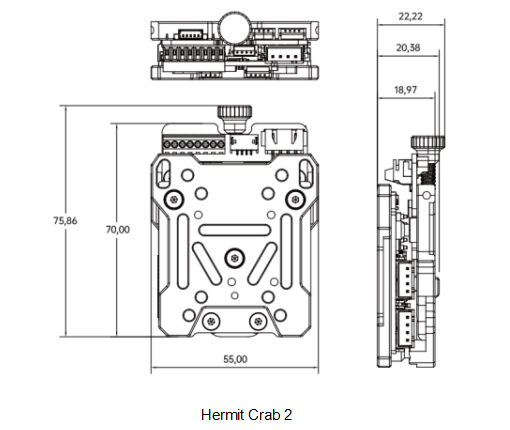
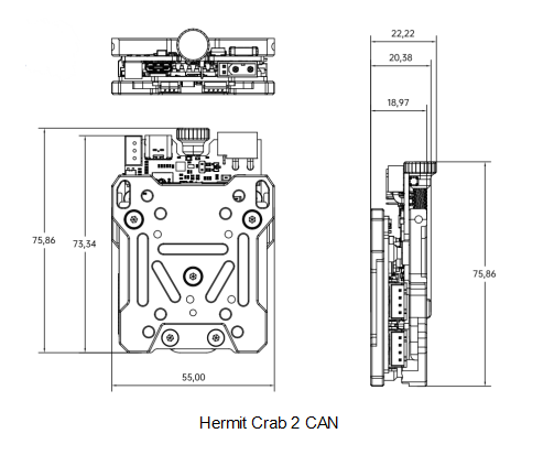
Dimension
Peripheral Interface
Pin Description

Wiring
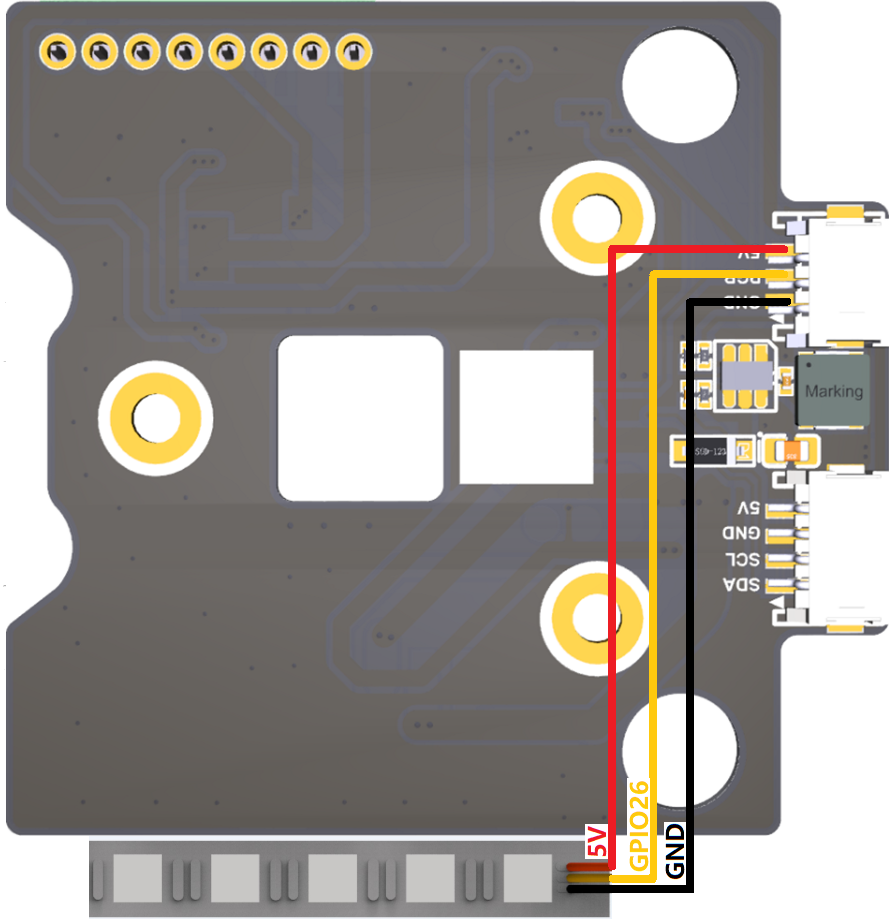
BLTouch Wiring

Fan Voltage Selection
4-Pin Fan
Use jumper to select voltage for VFAN0 between 5V or 12V.

2-Pin Fans
Use jumper to select voltage for VFAN1 (5V or 24V) and VFAN2 (12V or 24V).

RGB Wiring
Octopus Pro to Hermit Crab 2 Wiring

Firmware Setup(Hermit Crab 2 CAN)
Flash Katapult
Note: Katapult is for direct firmware updates via CAN bus. Skip this step if using DFU.
To flash Katapult on Raspberry Pi or CB1, refer to the following instructions to download the Katapult project:
https://github.com/Arksine/Katapult
1、Enter
cd ~
to go to the home directory, enter
git clone https://github.com/Arksine/Katapult
to download the Katapult project, then enter
cd Katapult
to navigate to the Katapult directory.
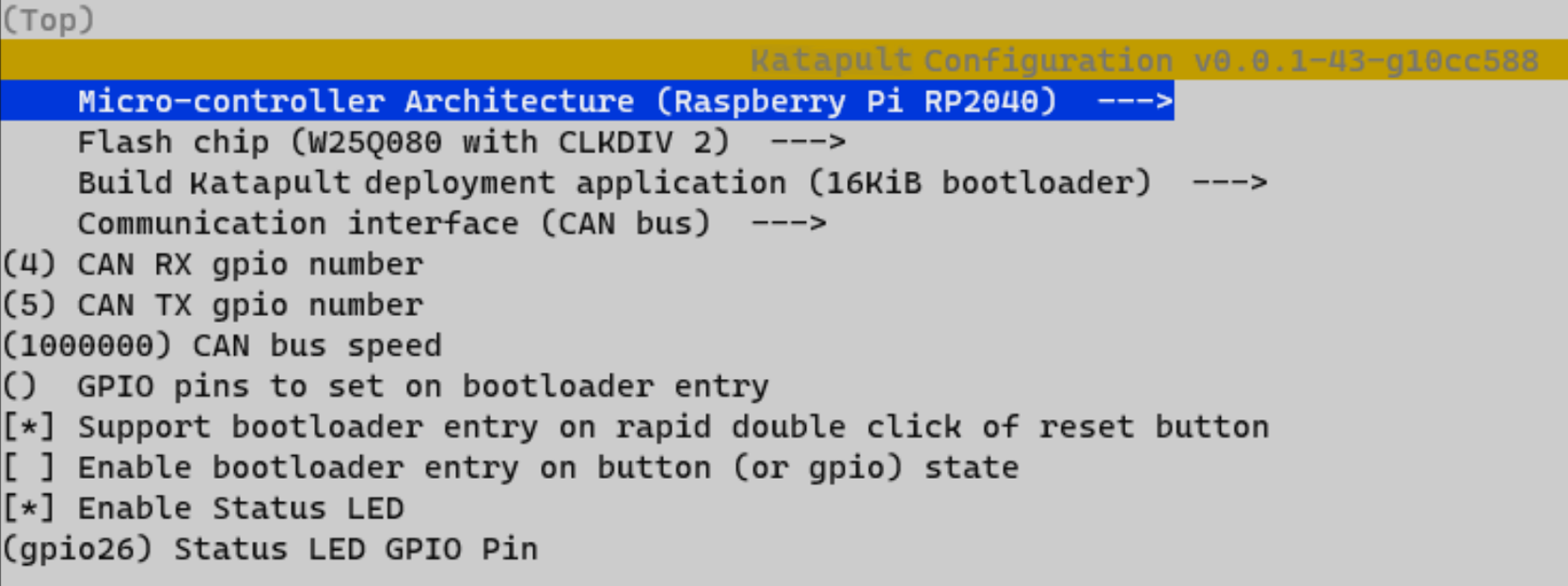
2、Enter
make menuconfig
and configure as shown in the image below.
3、Enter make to compile the firmware. When make is completed, the required katapult.uf2 firmware will be generated in the home/biqu/Katapult/out folder and can be directly downloaded to the computer on the left side of the SSH software.

4、Hold down the Boot button and connect to Raspberry Pi/CB1 with a Type-C cable. This allows the chip to enter DFU mode.
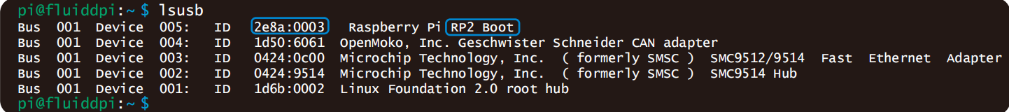
5、In the SSH terminal command line, enter lsusb to query the DFU device ID.

6、Enter the following command to flash Katapult
make flash FLASH_DEVICE=2e8a:0003
Replace 2e8a:0003 with the actual device ID obtained in the previous step.
7、After flashing, unplug the Type-C data cable.
Compiling Klipper Firmware
1、After SSH connects to CB1/Raspberry Pi, enter the following in the command line:
cd ~/klipper/
make menuconfig
Compile the firmware using the configuration below (if these options are not available, update the Klipper firmware source code to the latest version).

[*] Enable extra low-level configuration options Micro-controller
Architecture (Raspberry Pi RP2040) --->
If not using Katapult:
Bootloader offset (No bootloader) --->
Flash chip (W25Q080 with CLKDIV 2) --->
If using Katapult:
Bootloader offset (16KiB bootloader) --->
If using USB communication on Type-C:
Communication interface (USB) --->
If using CAN bus communication:
Communication interface (CAN bus) --->
(4) CAN RX gpio number
(5) CAN TX gpio number
(1000000) CAN bus speed
2、After configuring, enter ‘q’ to exit the configuration interface. When asked to save configuration, select ‘Yes’.
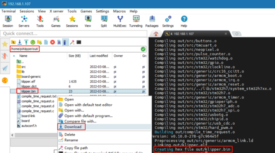
3、Enter make to compile the firmware. When make is completed, the required klipper.bin firmware will be generated in the home/pi/klipper/out folder and can be directly downloaded to the computer on the left side of the SSH software.
Firmware Update via KATAPULT
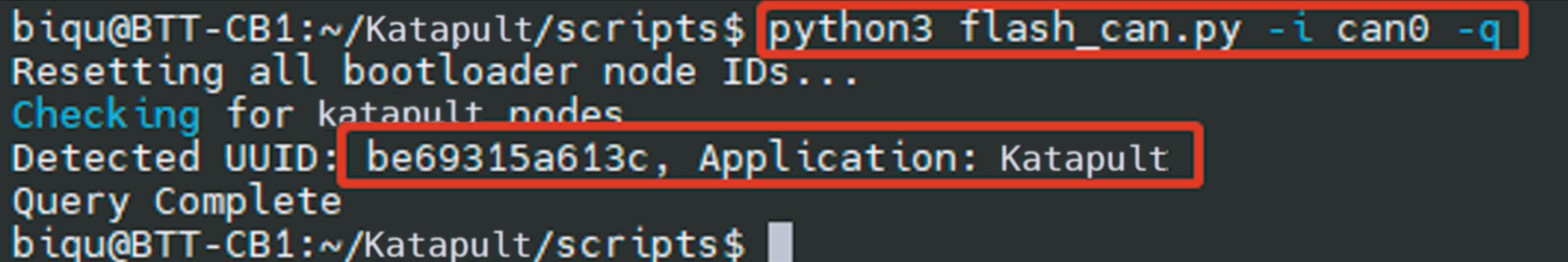
1、To use the CAN bus, ensure that the CAN bus cables are properly connected and that the jumper is inserted at the position of the 120R termination resistor. Enter
and then enter
to query the CAN bus ID (connect the CAN cable and power-on in advance). As shown in the image below, the UUID of the device is found.
2、Enter
replacing the UUID parameter after "-u" with the actual UUID on your board. Note: by this point, you should have already compiled klipper.bin using "make". Additionally, when selecting the bootloader offset in the Klipper menuconfig, use the 16KiB option since Katapult's Application start offset is 16KiB. The image below shows a successful flashing sequence.

3、Re-enter
to query. At this stage, the ‘Application’ has changed from Katapult to Klipper, indicating that Klipper is running normally.

Firmware Update via DFU
Raspberry Pi or CB1 firmware update through DFU:
1、Hold down the Boot button and connect to Raspberry Pi/CB1 with a Type-C cable. This allows the chip to enter DFU mode.
2、In the SSH terminal command line, enter lsusb to query the DFU device ID.
3、Enter cd klipper to navigate to the klipper directory, then enter
to start flashing the firmware (note: replace 2e8a:0003 with the actual device ID obtained in the previous step).
4、After flashing, enter
to query the device Serial ID (this ID is only available for USB communication, this step can be ignored when using CAN bus communication).
5、If using USB communication, there is no need to manually press the Boot button to enter DFU mode for subsequent updates after the first flashing is completed. Directly enter
to flash the firmware (note: replace /dev/serial/by-id/xxx with the actual ID obtained in the previous step).
6、If using CAN bus communication, unplug the Type-C data cable after flashing.
CAN Bus Configuration
For use with BIGTREETECH U2C module:

1、In the SSH terminal, enter
and add the following content:
Set the CAN bus speed to 1M (speed must match the speed set in the firmware (1000000) CAN bus speed). Save the changes (Ctrl + S) and exit (Ctrl + X), then enter
to restart Raspberry Pi.
2、Each device on the CAN bus will generate a canbus_uuid based on the MCU's UID. To find each microcontroller device ID, ensure the hardware is powered on and properly wired, then run:
3、If an uninitialized CAN device is detected, the above command will report the device's canbus_uuid:
4、If Klipper is already running and connected to this device, the canbus_uuid will not be reported.
Configuring Klipper
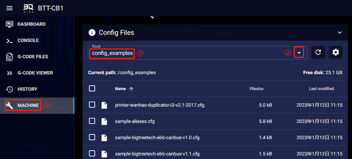
1、Access the mainsail web UI by entering the IP address of the BTT Pi or Raspberry Pi into the browser. Using the path shown in the image below, download the reference configuration named sample-bigtreetech-hermit-crab-2-canbus.cfg. If this file is not found, update the Klipper firmware source code to the latest version or use the link to download it from
GitHub: https://github.com/bigtreetech/HermitCrab
2、Upload the motherboard configuration file to Configuration Files.

3、Add the Hermit Crab configuration to the printer.cfg file:
[include sample-bigtreetech-hermit-crab-2-canbus.cfg]
4、Change the USB serial or CAN UUID within the configuration file to match the actual ID of the motherboard (USB serial or canbus).
5、Configure the specific functions of the module according to the instructions in the following link:
https://www.klipper3d.org/Overview.html
Precautions
1、When using CAN communication, check if this is used as a terminating device (one of the two devices at either end of the bus). If it is, ensure that the 120R position has a jumper inserted.
2、 When wiring, pay attention to the wire sequence and follow the Pin diagram for DIY instructions to avoid reversing the power line or connecting it to the CAN signal since this could cause damage to the Hermit Crab.
3、When flashing the firmware through the USB port without an external power supply, short the VUSB with a jumper to provide working voltage to the module.
4、The load current of the heater cartridge and fan interface should not be greater than the maximum rated current to prevent burning out the MOS tube.
FAQ
Q: Maximum current for heater cartridge and fan ports.
A: Maximum output current for heater cartridge port: 6 A.
Fan interface maximum output current: 1A, peak 1.5A.
Total current of heater cartridge + driver + fan should be less than 9A.
Q: Unable to update firmware through USB interface.
A: Ensure to short the VUSB with a jumper, and check that the power indicator light on the motherboard is on.