EZ31865
Product Profile
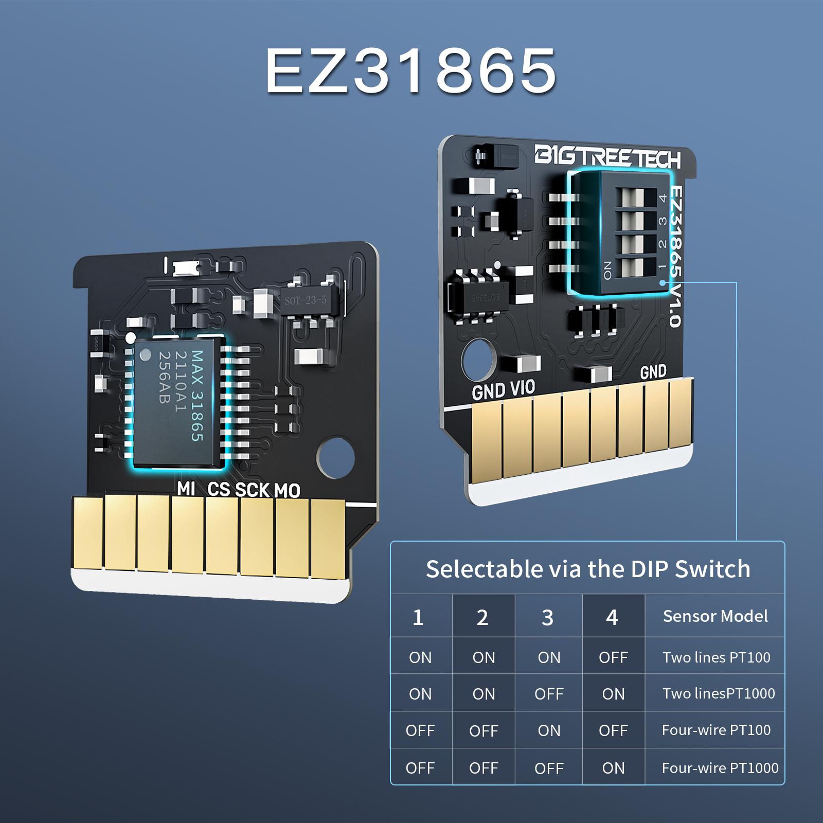
This module uses MAX31865 chip, supports two-wire, three-wire, four-wire PT1000 and PT100 temperature sensors, adopts the same package of motor drive module, easy to install, and uses VCCIO part of the power supply. Support 3.3V-5V power input.
Features Highlights
- Voltage range 4.5… 36V DC
- Low Rdson (HS+LS): 230 mΩ typical (TA=25C)
- Current ratings per H-bridge (typical at 25C): IMAX=5.0A (bridge peak current) IRMS=2.1ARMS (3A sine wave peak)
- Fully integrated lossless current sensing (ICS)
- Step/Dir interface with MicroPlyer™ step interpolation
- SPI & Single Wire UART
- Incremental encoder interface
- Highest resolution 256 microsteps per full step
- Flexible wave table and phase shift to match motor
- StealthChop2™ silent motor operation
- SpreadCycle™ highly dynamic motor control chopper
- Jerk-free combination of StealthChop and SpreadCycle
- StallGuard2™ & StallGuard4™ sensorless motor load detection
- CoolStep™ current control for energy savings up to 75%
- Passive braking and freewheeling mode
- Motor phase and chip temperature measurement
- General purpose analog input
- Full protection & diagnostics
- Overvoltage protection output
- Compact 5x5 TQFN32 package or 9.7x4.4 TSSOP38
Dimensions

Connection of Module Installation Method
The installation method is consistent with EZ series drive.
Modify the program of the motherboard, select the SPI mode of the motherboard driver jumper, and directly connect BIGTREETECH MAX31865V2.0 to the idle motor driver of the motherboard, and then connect the PT100/PT1000 thermistor to the corresponding original motor line On the interface (need to pay attention to the line sequence, subject to the actual motherboard, only support the motherboard that supports the SPI mode pluggable drive).
Interface Diagram

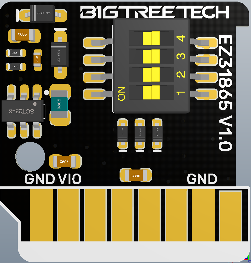
Pin_Definition
VIO—Positive power supply (3.3V-5V)
GND—Power negative
MO--data input
MI--Data output
SCK--Clock line
CS--Chip Select
DIP Switch Configuration
| 1 | 2 | 3 | 4 | Sensor Model |
| ON | ON | ON | OFF | Two Lines PT100 |
| ON | ON | OFF | ON | Two Lines PT1000 |
| OFF | ON | ON | OFF | Three Lines PT100 |
| OFF | ON | OFF | ON | Three Lines PT1000 |
| OFF | OFF | ON | OFF | Four Lines PT100 |
| OFF | OFF | OFF | ON | Four Lines PT1000 |
The 2/4 line is shown in the left figure. If the 3 line is used, it needs to be changed to the right figure (the factory default is 2/4 line)

3 wires can also use 2 wires, but the accuracy is slightly reduced (same as 2 wires).
Software Configuration
Marlin firmware supports the connection of up to two BTT PT1000&PT100 modules. The default is two-wire and four-wire common, through the configuration of Configuration.h and Configuration_adv.h files. The BTT PT1000&PT100 module can be a PT100 or PT1000 sensor, and different parameters need to be configured.
1.Configuration in Configuration.h:

TEMP_SENSOR_0 Set to -5: Use MAX31865 module on heater 0
TEMP_SENSOR_1 Set to -5: Use MAX31865 module on heater 1
Currently, only sensors 0 and 1 are configured as MAX31865 modules, others are not supported
Currently, only sensors 0 and 1 are configured as MAX31865 modules, others are not supported
If using PT100:
MAX31865_SENSOR_OHMS Set to 100
MAX31865_CALIBRATION_OHMS Set to 430
If using PT1000:
MAX31865_SENSOR_OHMS Set to 1000
MAX31865_CALIBRATION_OHMS Set to 4300
In the picture above: Temperature sensor 0 is configured as a PT1000 MAX31865 module
Temperature sensor 1 is configured as a PT100 MAX31865 module
The number of heating rods is 2 (#define EXTRUDERS 2)
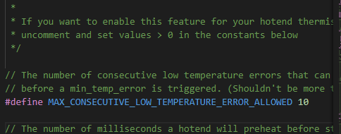
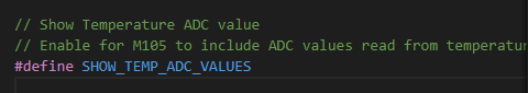
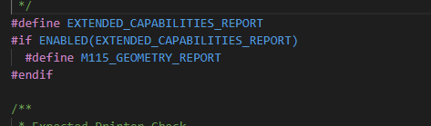
2.Configuration in Configuration_adv.h
#define THERMOCOUPLE_MAX_ERRORS 20
#define MAX_CONSECUTIVE_LOW_TEMPERATURE_ERROR_ALLOWED 10
#define SHOW_TEMP_ADC_VALUES
#define M115_GEOMETRY_REPORT

3.Use BTT-SKR motherboard V1.1 V1.3 V1.4 BTT-SKR V1.4 turbo
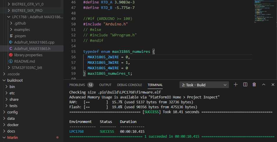
Note: After steps 1, 2 are completed, compile the program, and the program will report an error as shown below
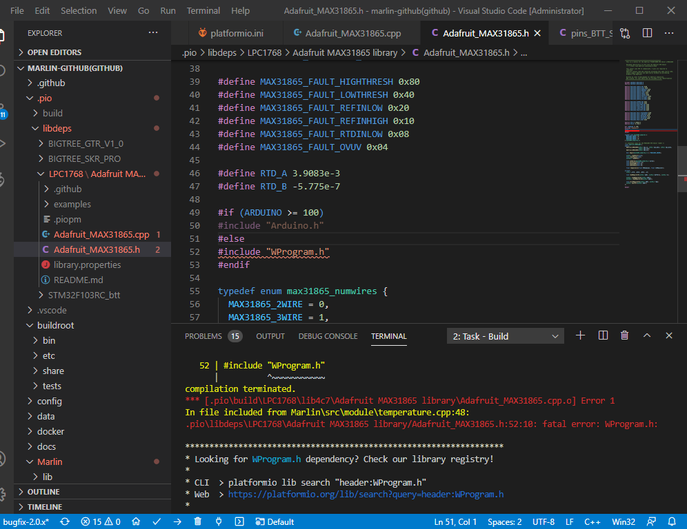
Make the following modifications in the file Adafruit_MAX31865.h Comment out (ARDUINO >= 100) to determine
BIGTREETECH motherboard and BIGTREETECH EZ31865 V1.0 module connection configuration:
The following is a tutorial for using the module on the BTT OCTOPUS V1.0 motherboard (marlin firmware)
1.Use a 4-wire PT1000 sensor and E3 drive interface. Select the SPI mode of the drive and use BTT EZ Driver Connector V1.0 to connect EZ31865.
2.Add pins in the pin file.
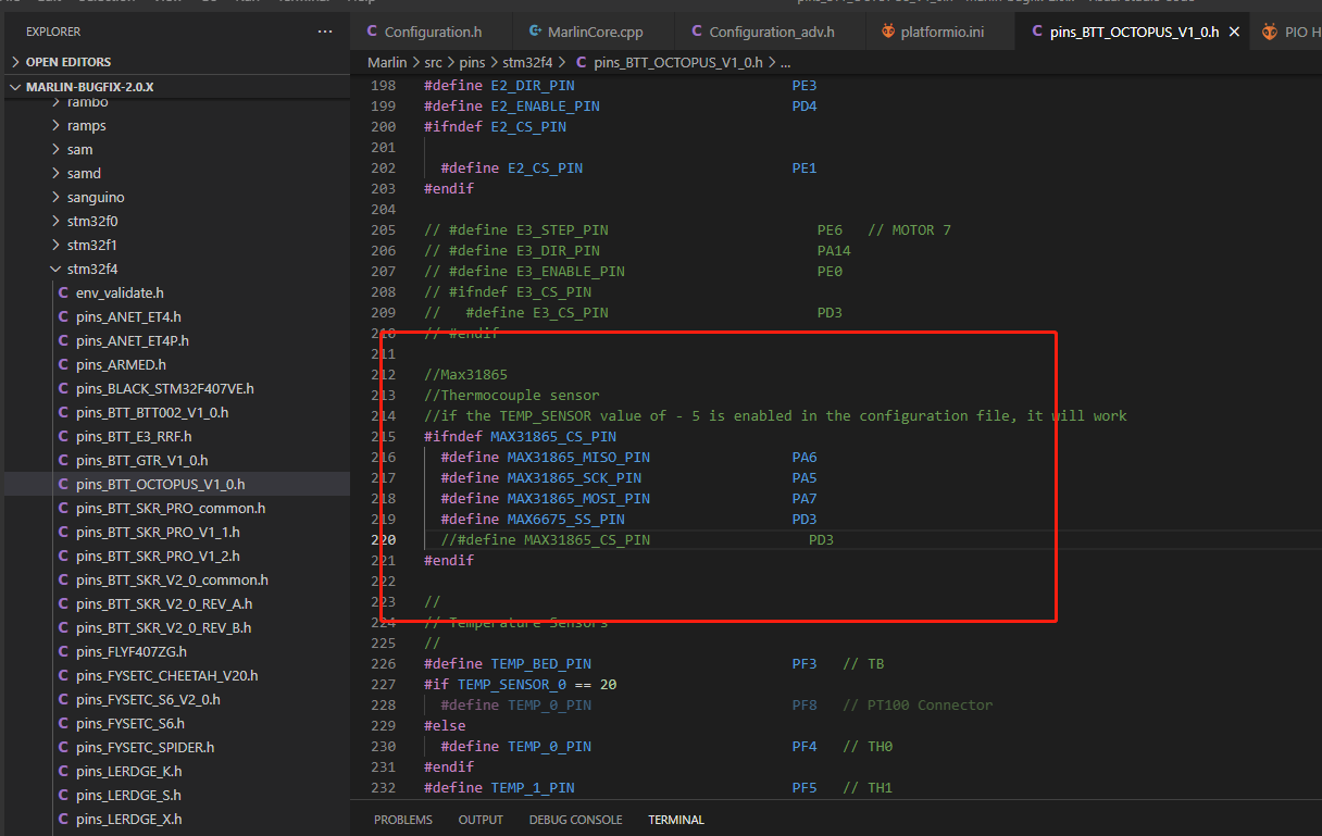

At present, to use this module on marlin, you need to define the MAX31865 chip select as MAX6675_SS_PIN, compile the bin file,and you can use it after updating
Precautions
- Please ensure that the power supply is disconnected when wiring or dialing the DIP switch
- Because this module uses SPI communication, motherboards that do not support SPI mode pluggable drivers cannot be used directly.
Product Purchase Link
Purchase Link:
https://biqu.equipment/products/bigtreetech-ez31865-v1-0
If you have any issues with the product, please submit a support ticket.
https://biqu3d.com/pages/submit-a-ticket
Navigation:
BIQU Official Website: http://biqu3d.com
BIGTREETECH Official Website: http://bigtree-tech.com
Online Store: https://biqu.equipment
BIGTREETECH Official Group: https://www.facebook.com/groups/bigtreetech
Discord: https://discord.gg/hhZsV7zk