Octopus Pro
Product Profile
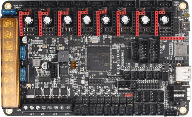
The BIGTREETECH Octopus-pro V1.0 is a powerful and feature rich, 3D printer motherboard that supports up to 8 60V stepper drivers with 9 stepper driver outputs in total. It is designed and manufactured by the 3D printing team of Shenzhen BIQU Innovation Technology Co., Ltd..
Features Highlights
- Uses a 32-bit ARM Cortex-M4 series. Option A comes with an STM32F446ZET6 main control chip with a core frequency of 180MHz and a flash capacity of 512kB.Option B comes with an STM32F429ZGT6 with a core frequency of 168MHz and a flash capacity of 1MB. For Klipper use, option A is likely sufficient.
- Supports running Klipper, Marlin and RRF.
- Voltage selection jumpers for each motor driver allow the user to independentlyselect the voltage routed to that driver. Select between the dedicated motor voltage input (up to 60V) and the main logic input (24V).
- Interfaces with a Raspberry Pi using emulated serial over USB or direct UART to any of the serial ports on the board.
- Interfaces with a Raspberry Pi using emulated serial over USB or direct UART to any of the serial ports on the board.
- Supports up to 4 hotend heaters.
- Provides separate power inputs for motors, bed heating and logic/fans/hotends.
- Supports 12V or 24V supply inputs (12V only supported on motor and bed. Logic must be > 14.1V and < 28V) with built in 12V (4A), 5V (8A) and 3.3V (1A) regulators to provide rails for peripheral use.
- Up to 6 PWM fans and 2 always-on fans with the ability to individually select the voltage rail that will drive each fan. Select from Vin, 12V or 5V.
- Flyback protection on PWM fan ports – Many people find that their fan ports become damaged after some time when using larger fans. This is because of the inductance in the fan coils. The octopus includes flyback protection on each fan port which will protect the FETs from damage caused by turning the fans on and off.
- Includes USB-C interface which supports an emulated serial port that allows printing via USB.
- Supports all versions of BIGTREETECH TFT screens and LCD12864 screens.
- Supports multiple languages such as English and Simplified Chinese and can easily switch between different languages (when using the BTT TFT).
- Includes a bootloader that allows firmware upgrades via the SD card. This offers a simple, efficient, and convenient way to update the firmware.
- Uses high-performance MOSFETs to increase heating efficiency while also reducing heat generation on the motherboard.
- Uses easily replaceable fuses
- Supports “print from SD card” and “print via USB OTG” using the integrated USB-A port.
- Provides two stepper outputs, connected in parallel, to the Z driver allowing for a parallel, dual Z axis drive.
- Supports firmware update via DFU mode. This is where the firmware is sent to the board directly from the PC and does not require a bootloader however this method is not recommended for novice users as discussed later in this document.
- Includes an onboard, 32K EEPROM (AT24C32).
- Provides an RGB LED interface.
- Provides a WiFi interface for ESP8266 based modules.
- Provides a built-in PT100/1000 interface using an integrated MAX31865 amplifier. The interface supports 2/3/4 wire connections.
- Thermistor input protection. This allows you to short a thermistor input directly to a voltage source (not that this makes it a good habit to pick up) up to Vin without causing damage to the motherboard.
- Supports BL Touch and various other ABL sensors.
- Provides a dedicated “PROBE” port for bed probes. This port is internally protected via an optocoupler which means that you don’t need to use a BAT85 diode.Additionaly, the octopus-pro includes a pull up resistor on the probe port which can be selected or deactivated using a jumper. This allows it to work with both NPN and PNP type probes.
- Supports CAN BUS using a 6P6C RJ11 interface, which offers the board the ability to interface with future expansion modules.
- Supports StallGuard for sensorless homing with TMC drivers
- Provides an SPI expansion port which can connect the SPI-based expansion modules.
- Supports the shutdown after printing function.
- Supports the power loss print resume function
- Includes inputs for up to 6 endstop switches and 2 filament runout interfaces.
- Provides an I2C expansion port for peripherals that communicate using that protocol.
- Includes a short circuit warning buzzer which will provide an audible alert when the current load on the 5V rail is exceeding what the regulator is able to produce.
Specifications
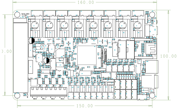
| Edge to edge size | 160*100mm |
|---|---|
| Mounting hole to hole size | 150*90mm |
| Microprocessor | ARM 32-bit Cortex™-M4 CPU: STM32F446ZET6 OR STM32F429ZGT6 |
| Recommended motherboard input voltage | DC15V – 28V |
| Motor input voltage range | DC12-60V |
| Bed input voltage range | DC12-28V |
| Motor drivers | Pluggable drivers supporting all popular driver types. |
| Motor driver sockets | MOTOR0, MOTOR1, MOTOR2_1, MOTOR2_2, MOTOR3, MOTOR4, MOTOR5, MOTOR6, MOTOR7 |
| Temperature sensor interfaces | TB, T0, T1, T2, T3. |
| Display interfaces | BIGTREETECH TFT touch screen, LCD12864, LCD2004, etc. |
| PC communication interfaces | USB Type-C with configurable BAUD |
| Expansion interfaces | Filament runout, power loss detection, automatic power down, BL Touch and many others |
| Supported print file format | G-code or whatever the firmware under use supports |
| Recommended slicing/interface software | Cura, IdeaMaker, Simplify3D, Prusa Slicer, Pronterface, Repetier-host, Makerware, etc… |
Dimensions
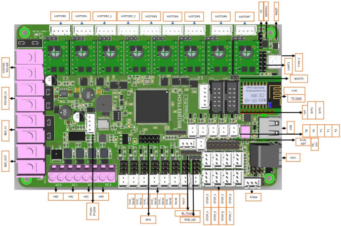
Interface Diagram
Pinout
The image below is a snippet taken from the PINS.pdf document. For better viewability please consult the PINS.pdf document.

Hardware Configuration
Note: The octopus-pro packs a ton of features which necessitates many components and connectors. Given the component and connector density it was not possible to include the silk screen for connector labels on the top. We recommend that you snap a picture of the bottom of the board before starting the installation so that you have a label reference on hand. If you forget to do so then you can always make use of the PINS.pdf file available on our github repo.
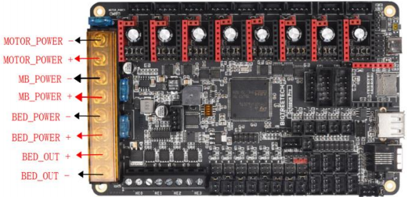
POWER WIRING
The octopus pro provides three separate power inputs: motherboard power, motor power, and bed heater power. This allows a user to use several power supplies with common grounds in order to ensure that they are able to provide the required power to each part of their system. The motherboard power is regulated using a number of switch-mode and low dropout power supplies to provide the supply rails of 12V, 5V and 3.3V.
The 12V, 5V and 3.3V rails are made available via various pins on the motherboard. Consult the PINS.pdf document to find a breakout header if you plan to use one of these supply rails. Take note that the 12V rail can supply up to 4A, the 5V up to 8A and the 3.3V up to 1A however, in order to prevent overloading the rails it is not recommended to load them to their maximum capacity since there are already various components on the motherboard which also take their supply from them.
Power wiring is as shown below (look on the underside of your board to quickly identify the purpose of each input if the pins file is not on hand). The positive (red) wire from the power supply goes to the terminal marked +. The negative (black) wire from the power supply goes to the terminal marked -. The polarity (+ and -) is also silk screened onto the underside of the board.
Note: DO NOT alter the board wiring with the power on and be sure to get the polarity correct otherwise you can damage the motherboard.
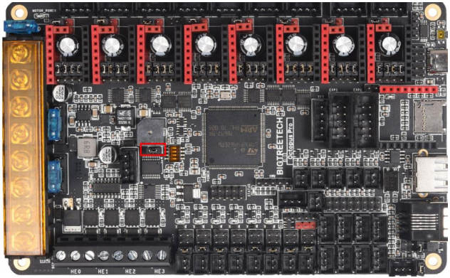
MCU POWER JUMPER
The Octopus can be powered using the USB-C port by inserting the jumper as shown below. This can make it easier to compile and download firmware directly to the motherboard using DFU mode.
If you do not connect this jumper then you must provide the board with power via the main input supply if you would like to communicate via USB-C.
Hardware Installation
AUTOMATIC POWER DOWN WIRING
When using the BIGTREETECH Relay V1.2 module, the wiring can be performed as shown in the figure below.
Note: Since power will still be supplied to the Relay 1.2 module after it has cut power to the motherboard, it is extremely dangerous to touch the it while the printer is still connected to mains. Always remove all mains power when working on this wiring.
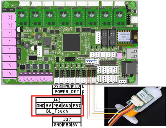
BL TOUCH WIRING
When using a BL Touch, wire it to the motherboard as shown in the figure below. As always, never perform any work on the motherboard with power applied.
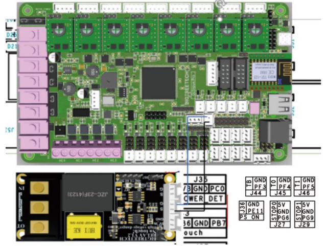
POWER LOSS RECOVERY MODULE WIRING
When using the BIGTREETECH mini UPS, wire it to the motherboard as shown in the figure below. As always, never perform any work on the motherboard with power applied.

RGB LED WIRING
When using the motherboard with RGB LEDs you should wire them as shown in the image below. The exact pinout of the connector can be found on the silkscreen on the underside of the motherboard.

RASPBERRY PI WIRING
The motherboard supports a connection to a Raspberry Pi for printing. There are several connection options available to connect to a raspberry pi. Simplest of all is to connect the raspberry pi directly to the USB-C port which will emulate a virtual serial port on the pi. However, if you have another need for the USB-C port you are still able to connect the raspberry pi to the motherboard using a direct serial connection over UART or SPI.
Dedicated UART and SPI pin headers have been made available on the motherboard for this purpose with the pin mappings conveniently printed in silkscreen on the underside of the board for each. It is beyond the scope of this manual to detail exactly how to connect the raspberry pi to either of these headers however there is an abundance of material online that explains how to interface a raspberry pi to an external device over either of these serial busses.
5V power for the raspberry pi is provided via the dedicated Raspberry pi header (UART2). Consult the PINS.pdf document for the exact pinout of this header.

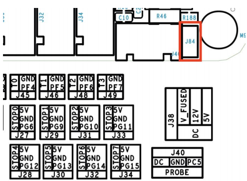
PROBE PORT WIRING
The probe port has been provided to allow users to interface bed probes directly to the motherboard without the need for a BAT85 diode to act as a protection against high voltages. The probe signal pin connects to an internal optocoupler that in turn triggers the pin connected to the microcontroller.
Depending on the type of probe you are using, you may need to add a jumper to activate the internal 12k pull up resistor between the probe positive voltage rail and the probe signal pin. This will be the case if you are using an “NPN” style probe where the output pulls to ground when it is active. You can tell this by checking the output of your probe using a multimeter. If it floats when it is not active (with nothing else connected to it) and then goes to ground when it is active, it is an NPN style probe. If it goes to the positive rail when active then it is a PNP style probe. The image below shows where the jumper to activate the 12k pull up resistor is located.
Regardless of the kind of probe you are using, you will need to enable the internal pulldown resistor on the probe input pin in order for it to generate an output signal. Please refer to the pin configuration instructions for the specific firmware that you are using to find out how to enable a pull down resistor on the probe input pin (PC5).
Refer to Section 4.2 for further information on how to configure the voltage used by the probe port.
STEPPER DRIVER OPERATIONAL MODES
STEP/DIR MODE
If you are using drivers that do not support configuration over a serial port then you will need to operate them in step/dir mode and set the jumpers beneath the stepper driver according to the microstepping you desire.
Each driver will have its own microstepping table so we do not attempt to speak on behalf of the driver manufacturer in our manual. Please consult the datasheet of your driver to determine what signals need to be applied to the microstepping configuration pins in order to achieve the microstepping you desire.
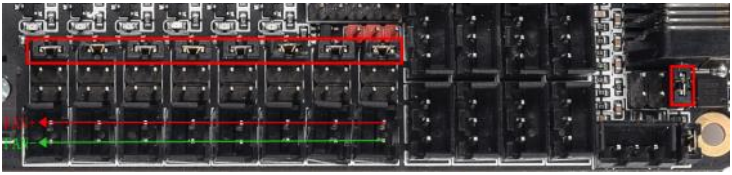
Nevertheless, below you will see a figure which will help you to identify which jumpers correspond to the pins that your drivers will use to configure microstepping and we have additionally included a section in appendix A1 which contains the microstepping tables for some of the most common drivers. This should be viewed as a convenience to the user and we still recommend that you consult the datasheet of your driver manufacturer.
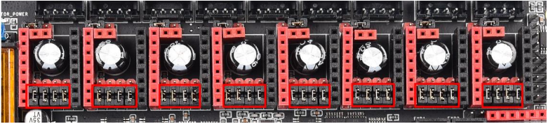
In the above image the red rectangle isolates the groups of driver pins. For the purpose of running the drivers in step/dir mode the pinout can be described as per the table below.
Note that this is not the actual pinout but rather a simplification for step/dir mode.

Connecting jumpers between the lower two rows will set the middle pin (MS) to 5V except for the jumpers in the first column where it will connect SLP and RST. Note that if your stepper driver requires 0V to be present on any of the pins then there is actually no need to connect a jumper to that pin when running in step/dir mode and connecting a jumper in this instance could cause interference since those lines are used for the SPI bus.
Note that if you use an A4988 or a DRV8825 driver, you must connect RST and SLP.
For details, please click: https://z1996xm.github.io/BIGTREETECH/Tutorials.html
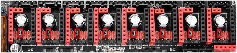
UART MODE
When using a driver in UART mode, connect the jumpers beneath that driver as show in the image below.
SPI MODE
When using a driver in SPI mode, connect the jumpers beneath that driver as shown in the image below.

MOTHERBOARD JUMPER SETTINGS
MOTOR POWER SELECTION JUMPERS
Each motor driver on the octopus pro can have the voltage used by it configured via a jumper.
Note: Before powering your octopus pro, always double check the driver voltage jumpers to ensure that the correct voltage is being routed to each driver. Sending a high voltage to a driver that is not rated for it is likely to destroy it and may even cause damage to the motherboard.
Setting the jumper for any given driver to the right, as shown in the image below, will provide the motherboard input voltage for that driver to use. Generally the motherboard uses 24V.

Setting the jumper for any given driver to the left, as shown in the image below, will provide the motor input voltage for that driver to use. This can be up to 60V.

Note: Never remove or insert a jumper when power is applied to either the board input or the motor input.
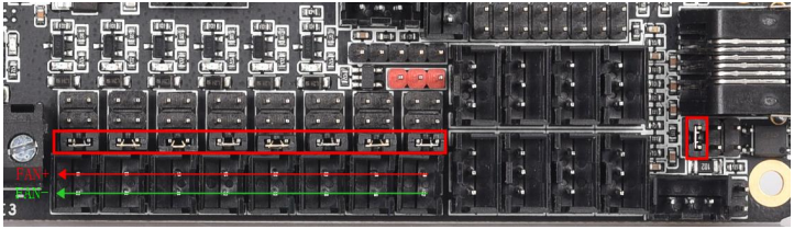
FAN AND PROXIMITY SWITCH VOLTAGE SETTINGS
The Octopus features 6 PWM fan outputs and two “always on” fan outputs. There is also a dedicated pin header for a proximity sensor or probe.
All of the fan outputs and the proximity sensor input can individually have the voltage supplied by their pin header selected by configuring the jumpers associated with each header.
Configure the jumpers as below to select 24V (note that all are shown in the same configuration even though they can be individually configured).
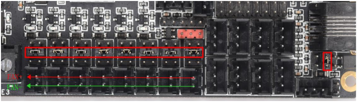
Configure the jumpers as below to select 12V.
Configure the jumpers as below for 5V.
Note: Since the jumpers carry a voltage rail directly from one of the regulators or from the input, if you short the jumpers in any way other than the shown connections, you will likely cause damage to the motherboard. When connecting the fan, make sure that you connect the positive terminal to the positive output as shown in the images.
STALLGUARD JUMPER SETTINGS
The “diag” jumpers which are used to connect the diagnostic output pin to the endstop inputs for drivers which support the stallguard feature (TMC2209/TMC2226, etc…) can be found in the location shown in the image below.
The exact diag numbering can be found by looking at the pins file or the silkscreen beneath the board.

PT100/PT1000 DIP SWITCHES
The PT100 amplifier supports 2,3 and 4 wire connections to the board. However, the DIP switch needs to be configured for the setup that you are using.
You can find the DIP switch in the location shown in the image below. Note that the DIP switch has switch numbers and the “on” position printed on it.

Select the connection arrangement for your thermistor according to the table below. Bear in mind that you will still need to configure your firmware using the correct sense resistor values which will be 430 for the PT100 and 4300 for the PT1000.
| 1 | 2 | 3 | 4 | Sensor model |
| ON | ON | ON | OFF | Two-wire PT100 |
| ON | ON | OFF | ON | Two-wire PT1000 |
| OFF | ON | ON | OFF | Three-wire PT100 |
| OFF | ON | OFF | ON | Three-wire PT1000 |
If you are using a three-wire arrangement, then you will also need to make a small adjustment to an SMD resistor on the board. The image below shows the factory default resistor setting in the blue box (2/4 wire arrangement). Using a 3 wire arrangement will require you to move the resistor from the blue box into the red box and then to leave the pads in the blue box unpopulated. These resistors are 0 so if you do not feel comfortable soldering them back in place you can always just create a solder bridge between the pads instead, selecting the pads appropriate to your arrangement.

Software Installation
COMMUNICATING WITH THE MOTHERBOARD
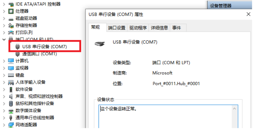
After connecting the motherboard to a computer via a USB cable, the driver will be automatically installed (windows, linux and macos). Upon installation of the driver the motherboard should automatically enumerate as a virtual serial device which can be used for data transfer. If it fails to do so, you can visit our GitHub website: https://github.com/bigtreetech?tab=repositories and find the corresponding repository to download the driver.
If you would like to confirm that the driver has been installed correctly you can access the device manager in windows and look for a virtual com port when the motherboard is plugged in. In the image below the motherboard has been assigned COM7 however your operating system may assign it any available COM port number. Other operating systems will list serial ports in a different manner.
MOTHERBOARD FIRMWARE SUPPORT
Marlin, Klipper and RRF (429 variant) all support the Octopus Pro. You can compile and configure you firmware variant of choice according to the methods specified by the developers of that firmware. In time, configuration files for different firmware distributions will be made available on the octopus-pro github. Covering how to compile firmware using VSCode is beyond the scope of this manual however there is an abundance of information online which explains how to set up VSCode on your machine and how to configure Marlin thereafter. Good places to start are provided for your convenience in the links below:
• https://marlinfw.org/docs/basics/install_platformio_vscode.html
• https://www.youtube.com/watch?v=eq_ygvHF29I
Once you have either compiled your own version of Marlin or downloaded a pre-compiled version, you can install it by following the steps below:
- Make sure that the firmware binary is named “firmware.bin”. Any other name will be rejected by the bootloader.
- Use an SD card that has been formatted using the SD formatter tool here: https://www.sdcard.org/downloads/formatter/
- Copy the firmware binary file to the SD card.
- Insert the SD card into the motherboard and reset it.
- Remove the SD card and check that the file has changed name to “FIRMWARE.CUR”. This will confirm that the firmware was successfully installed.
If you are using Klipper then please ensure that you have the following settings enabled for the 446 variant. Take careful note of the crystal oscillator frequency which is 12MHz and differs from the 429 variant.
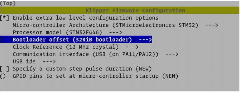
The 429 variant of the board makes use of a different frequency crystal oscillator (8MHz) and therefore the klipper configuration needs to be adjusted slightly as show in in the image below.

PRECAUTIONS
The precautions listed in this section should not be overlooked. They have been included as reminders to prevent damage to your motherboard.
- Never work on the motherboard with power applied.
- Always double check all jumpers and wiring before applying power. Improper jumpers or wiring can cause damage to the motherboard and possibly even peripherals that it interfaces with.
- The motherboard can power heated beds up to 300W. If you are using a bed that operates at a higher power then you will need to use an external MOSFET. Do not connect a voltage source greater than 28V to this input.
- Never short circuit the 3.3V, 5V, 12V or 24V supplies to each other. Doing so will let out some smoke and BTT will not be able to put it back for you.
- You cannot power external devices using the USB-C interface. It is designed for data only.
- Always consult the PIN.pdf diagram when making jumper connections or wiring changes. Assuming a connection order may result in damage to the motherboard.
- It is recommended to update the firmware using SD card. Using DFU (direct programming via the USB port) will overwrite the bootloader meaning that you will no longer have the option to update via SD card unless you reflash the bootloader.
Product Purchase Link
Purchase Link:
https://biqu.equipment/products/bigtreetech-octopus-pro-v1-0-chip-f446
If you have any issues with the product, please submit a support ticket.
https://biqu3d.com/pages/submit-a-ticket
Navigation:
BIQU Official Website: http://biqu3d.com
BIGTREETECH Official Website: http://bigtree-tech.com
Online Store: https://biqu.equipment
BIGTREETECH Official Group: https://www.facebook.com/groups/bigtreetech
Discord: https://discord.gg/hhZsV7zk