Octopus MAX EZ

Product Profile
BIGTREETECH Octopus MAX EZ, a 32 bit motherboard, is an upgraded version of Octopus Pro developed by the 3D printing team of Shenzhen BIQU Innovation Technology Co., Ltd.. Its self-developed stepper motor sockets enhance safety and user experience, and it adds a series of features that Octopus Pro does not have, greatly enhancing its DIY capabilities.
Features Highlights
- 32 bit 550 MHz ARM Cortex-M7 series STM32H723ZET6 MCU.
- Onboard BOOT button to enable DFU mode to update bootloader.
- The thermistor circuit is protected to prevent MCU damage from shorted heated bed and heater cartridge connections.
- Selectable voltage (24V, 12V, 5V) for CNC fan, no more need for external stepdown thus preventing board damage from user error.
- Upgraded with eFuse protection, which responses faster with strong protection, effectively protecting the motherboard from being damaged caused by short circuits, over-current, electric spark, etc.
- MCU firmware can be upgraded via SD card, or use DFU via Klipper's make flash command.
- 10 EZ driver sockets, working with pinless driver, safer to use; Onboard SPI and UART, can be used by simply setting in the firmware, no need for a jumper.
- Support power loss recovery, filament runout sensor, CAN, auto power-off, BLTouch, RGB, etc.
- Replaceable fuse for easy maintenance.
- 3 x 4 pins fan ports, also for connecting water cooling system.
- Onboard proximity switch port, supports NPN and PNP types, 24V, 12V, 5V voltage selectable.
- Onboard SPI interface for connecting acceleration sensor to enable Klipper's input shaping.
Specifications
| Dimensions | 160mm x 100mm for details please refer to BIGTREETECH Octopus MAX EZ V1.0-SIZE.pdf |
|---|---|
| Mounting Size | Please refer to BIGTREETECH Octopus MAX EZ V1.0-SIZE.pdf |
| MCU | ARM Cortex-M7 STM32H723ZET6 550MHz |
| Driver Input Voltage | 24V, HV(≤56V) Selectable |
| Motherboard Input Voltage | VIN=DC12V or DC24V |
| Heated Bed Input Voltage | BED IN=DC12V or DC24V |
| Logic Voltage | DC 3.3V |
| Heater Connection | Heated Bed (HB), Heater Cartridge (HE0, HE1, HE2, HE3) |
| HB Port Max Current | 10A Continuous, 12A Instantaneous |
| Heater Cartridge Max Current | 5.5A Continuous, 6A Instantaneous |
| Fan Port | 2 pins CNC Fan (FAN0, FAN1, FAN2, FAN3), 4 pins CNC Fan (FAN4, FAN5, FAN6), Always On (24V FAN x 2).CNC Fan and MFAN Voltage Selectable (5/12/24V) |
| Fan Port Max Current | 1A Continuous, 1.5A Instantaneous |
| Overall Max Current (Heater Cartridge+Driver+All Fans) | <12A |
| Expansion Port | BLTouch (Servos, Probe), PS-ON, FWS, PWRDET, RGBx2, SPI,IND-Probe, CAN, WIFI, TFT |
| Motor Driver | Support EZ5160, EZ2209, EZ2225, EZ2226, EZ2208, EZ2130... |
| Driver Mode | SPI, UART |
| Motor Socket | Motor1, Motor2, Motor3 (Dual Motor Sockets), Motor4, Motor5,Motor6, Motor7, Motor8, Motor9, Motor10 10 Channels in Total |
| Thermistor | 5 x 100K NTC, four of which are selectable for NTC and PT1000 |
| Display | MINI12864 (FPC Connection), TFT Serial |
| PC Connection | Type-C |
| Supported Kinematics | Cartesian, Delta, Kossel, Ultimaker, CoreXY |
| Recommended Slicer/Console | Cura, Simplify3D, Pronterface, Repetier-host, Makerware |
Dimensions

Peripheral Port
Connector Diagram

Pinout Diagram

Hardware Configuration
USB Power Supply
After the Octopus MAX EZ has been powered, the Red light D32 on the left side of the MCU will light up, indicating power on. When using only USB to power the board or to supply power via USB, please insert the jumper cap onto the VUSB.

Stepper Motor Driver
UART/SPI Mode of Driver
Set in the firmware, no need for a jumper.
TMC Driver DIAG (Sensorless Homing)
When using sensorless homing, place jumpers according to the diagram below, there is no need to cut the DIAG pin off when not being used. (Motor1-Motor6).

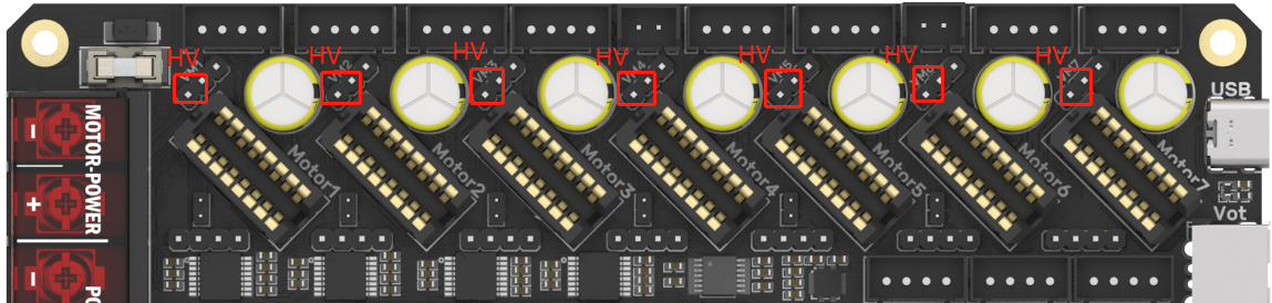
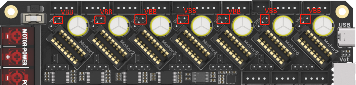
Driver Voltage Selection
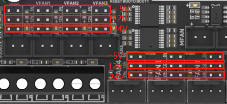
Voltage Selection for CNC Fan
The output voltage can be set to 5V, 12V or 24V through a jumper cap. (MFAN and FAN6 share the power supply VFAN6).
Note: we are not responsible for fan burnout caused by incorrect voltage selection. Please confirm the voltage the fan supports before selecting the voltage.
100K NTC or PT1000 Setting
When using 100K NTC, no jumpers need to be connected, the pull-up resistance of TH0-TH3 is 4.7K 0.1%. When using PT1000, the pins indicated in the picture below need to be connected via jumpers, parallel connection of 4.12K 0.1% resistors, the pull-up resistance of TH0-TH1 is 2.2K.
(Note: this method has a much lower accuracy than the MAX31865 in reading temperature.)

BLTouch Wiring

Auto Power Off (Relay V1.2) Wiring

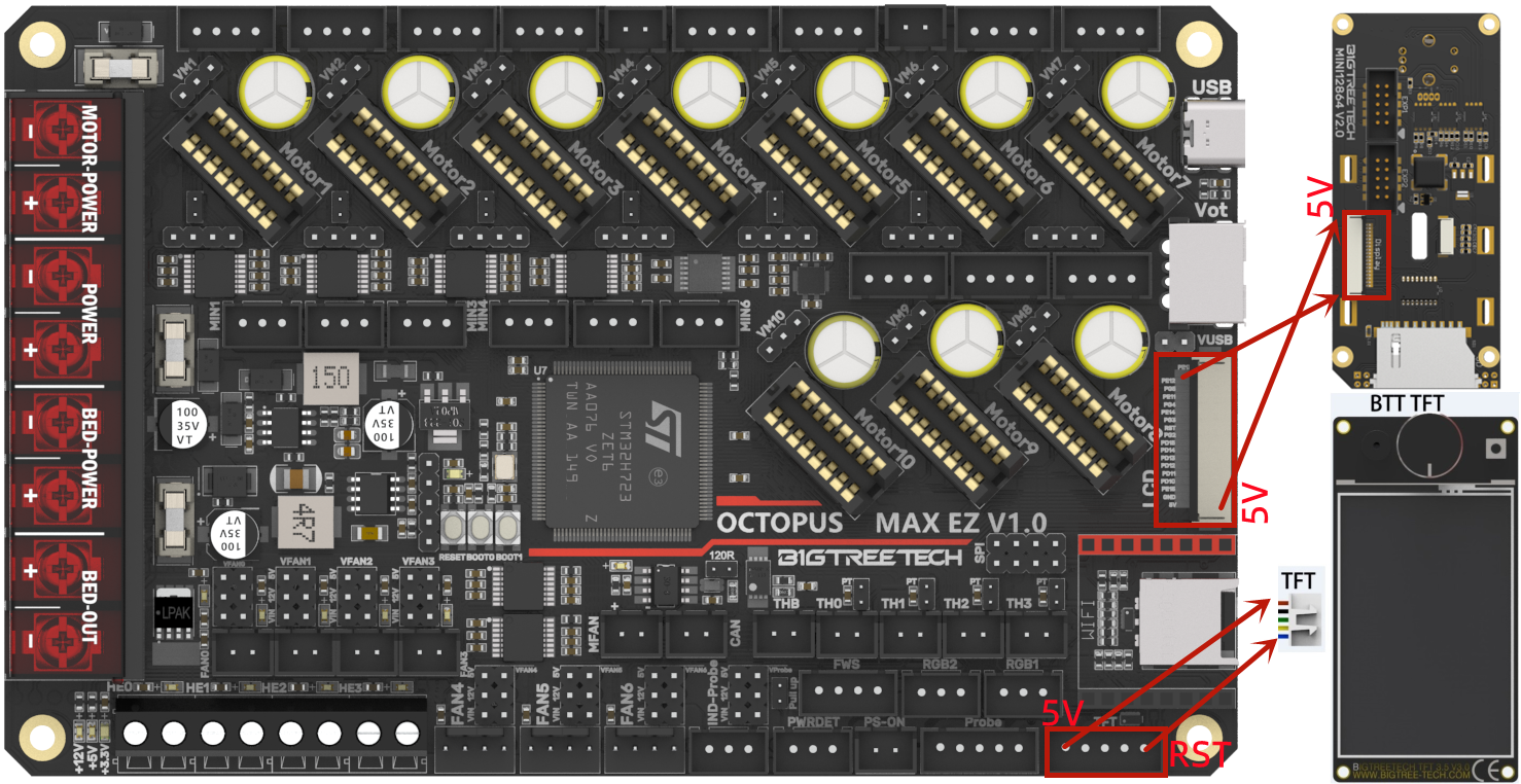
Connecting with MINI12864/TFT Screen
RGB Wiring

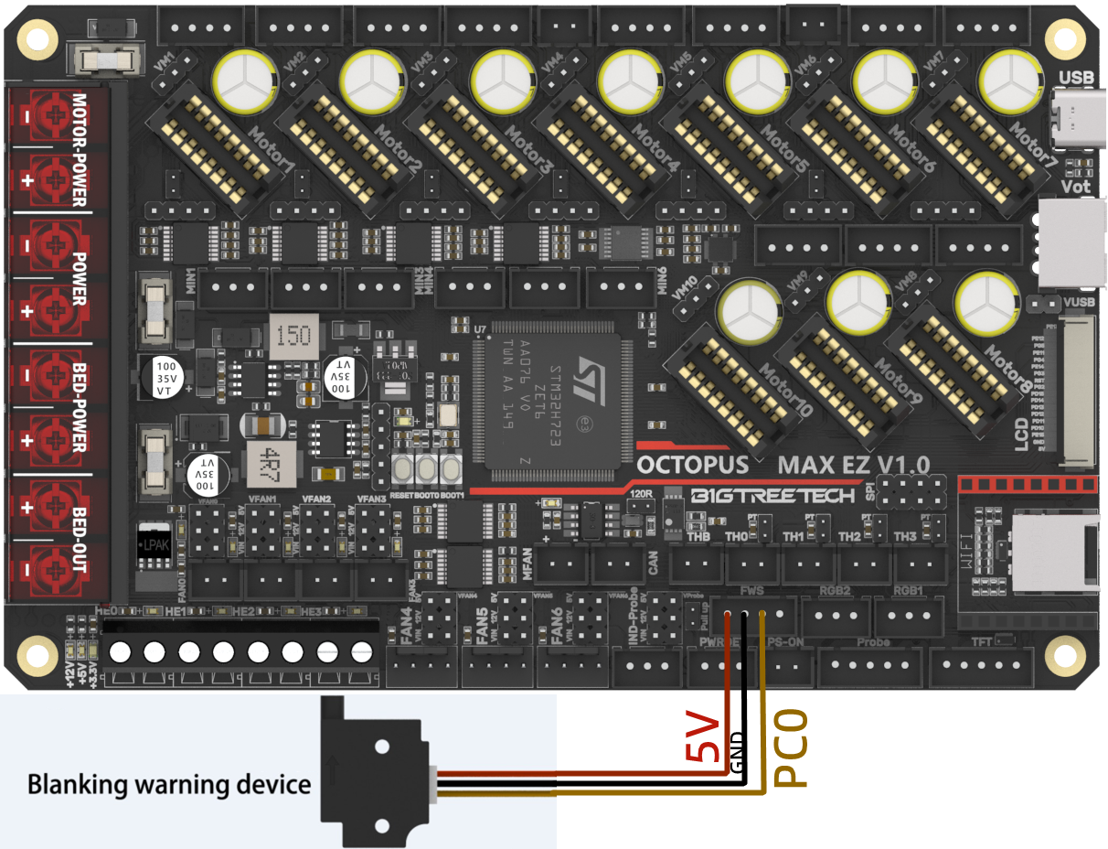
Filament Sensor Wiring
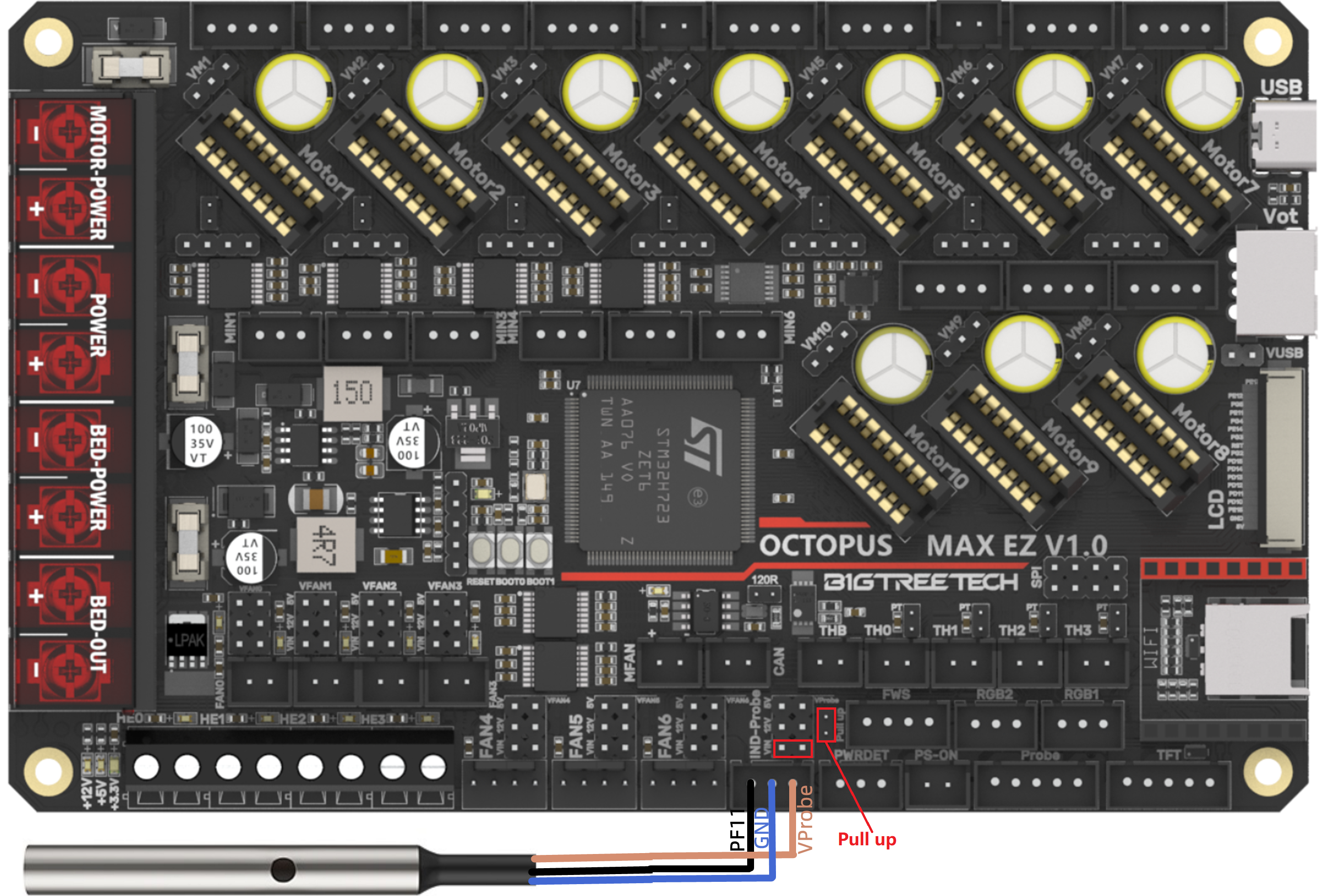
Proximity Switch Wiring
As shown in the figure below, 24V as an example, normally open (NPN type), no need for shorting through a jumper cap:

As shown in the figure below, 24V as an example, normally closed (PNP type), need for shorting through a jumper cap.
Wiring of 4 pins CNC Fan and Water Cooling System
(12V as an example:)

Software Installation
Marlin
Install Compiling Environment
https://github.com/bigtreetech/Document/blob/master/How%20to%20install%20VScode%2BPlatformio.md
https://marlinfw.org/docs/basics/install_platformio_vscode.html
Refer to the link above for tutorial on installing VSCode and PlatformIO plugin.
Download Marlin Firmware
1.Download the newest bugfix version of Marlin from the official website: https://github.com/MarlinFirmware/Marlin/tree/bugfix-2.0.x
2.Download pre-configured firmware from our GitHub page: https://github.com/bigtreetech/BIGTREETECH-OCTOPUS-Max-EZ
Configure Firmware
Open Marlin Project
You can open Marlin in VS Code in one of several ways:
- Drag the downloaded Marlin Firmware folder onto the VScode application icon;
- Use the Open... command in the VSCode File menu;
- Open the PIO Home tab and click the Open Project button.
Compiling Environment
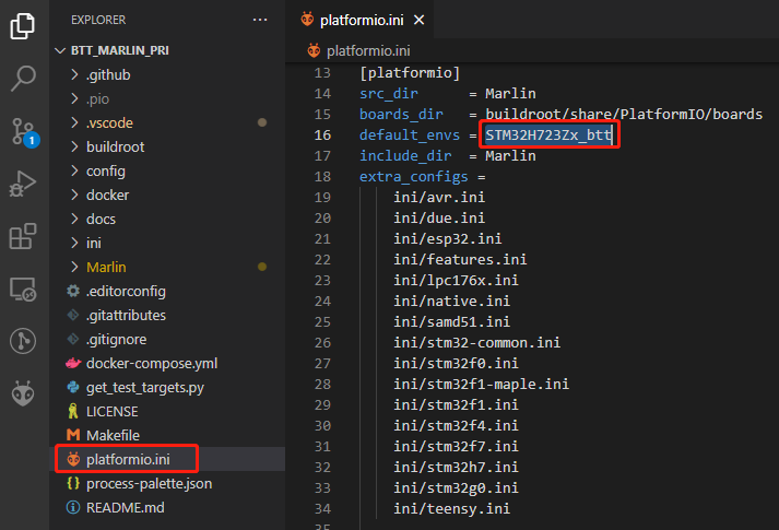
Open platformio.ini file and change default_envs to STM32H723Zx_btt.
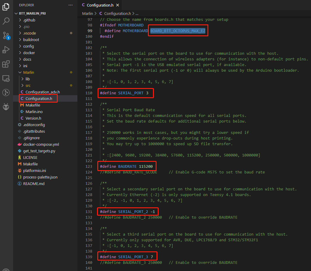
Configure Motherboard and Serial Port
Set MOTHERBOARD to BOARD_BTT_OCTOPUS_MAX_EZ
#define MOTHERBOARD BOARD_BTT_OCTOPUS_MAX_EZ
#define SERIAL_PORT 3 (enable TFT serial port)
#define BAUDRATE 115200 (set baudrate to the same as the communication device)
#define SERIAL_PORT_2 -1 (enable USB serial port)
#define SERIAL_PORT_3 7 (enable WIFI serial port)

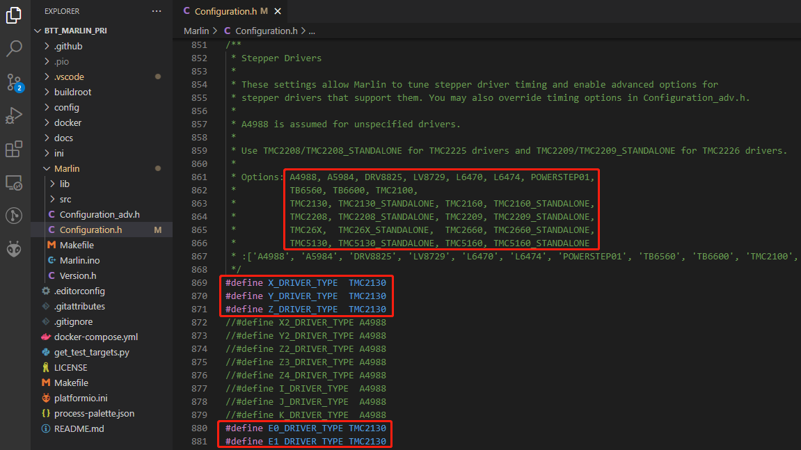
Configure Stepper Driver
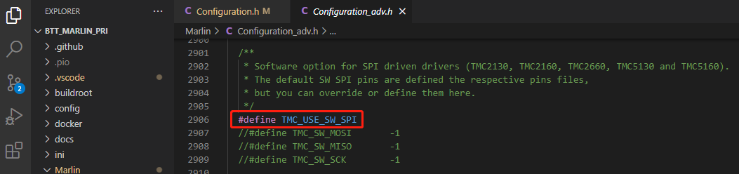
When using SPI mode, you need to enable TMC_USE_SW_SPI in Configuration_adv.h
#define TMC_USE_SW_SPI
Sensorless Homing
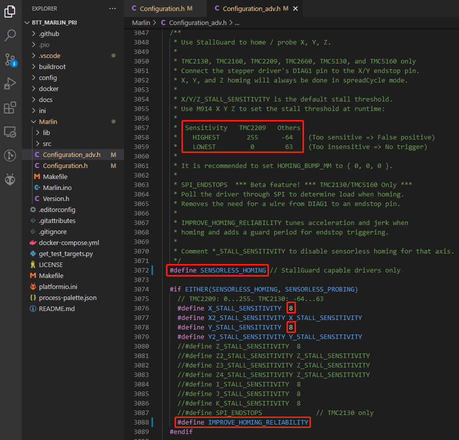
#define SENSORLESS_HOMING // enable sensorless homing
#define xx_STALL_SENSITIVITY 8 // sensitivity setting, TMC2209 range from 0 to 255, higher number results in more sensitive trigger threshold, sensitivity too high will cause endpoint to trigger before gantry actually moves to the end, lower number results in less sensitive trigger threshold, too low of sensitivity will cause endpoint to not trigger and gantrying continue. Other drivers range from 63 to -64, lower numbers result in a more sensitive trigger threshold.
#define IMPROVE_HOMING_RELIABILITY // can be used to set independent motor current for homing moves(xx_CURRENT_HOME) to improve homing reliability.
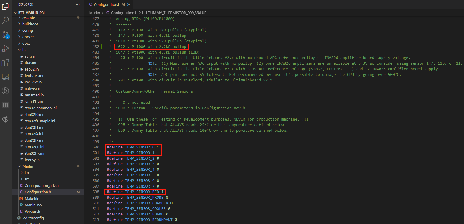
100K NTC or PT1000
When using 100K NTC, pull-up resistance is 4.7K, when using PT1000, pull-up resistance is 2.2K, set sensor type to 1 for 100K NTC +4.7K pull-up resistance, 1022 for PT1000 + 2.2K pull-up resistance. (Note: this method has a much lower accuracy than the MAX31865 in reading temperature.)
#define TEMP_SENSOR_0 1
#define TEMP_SENSOR_1 1
#define TEMP_SENSOR_BED 1
BLTouch
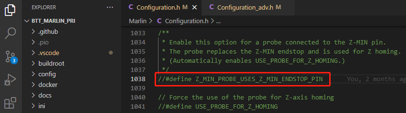
//#define Z_MIN_PROBE_USES_Z_MIN_ENDSTOP_PIN //
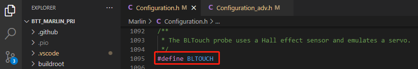
#define BLTOUCH // Enable bltouch
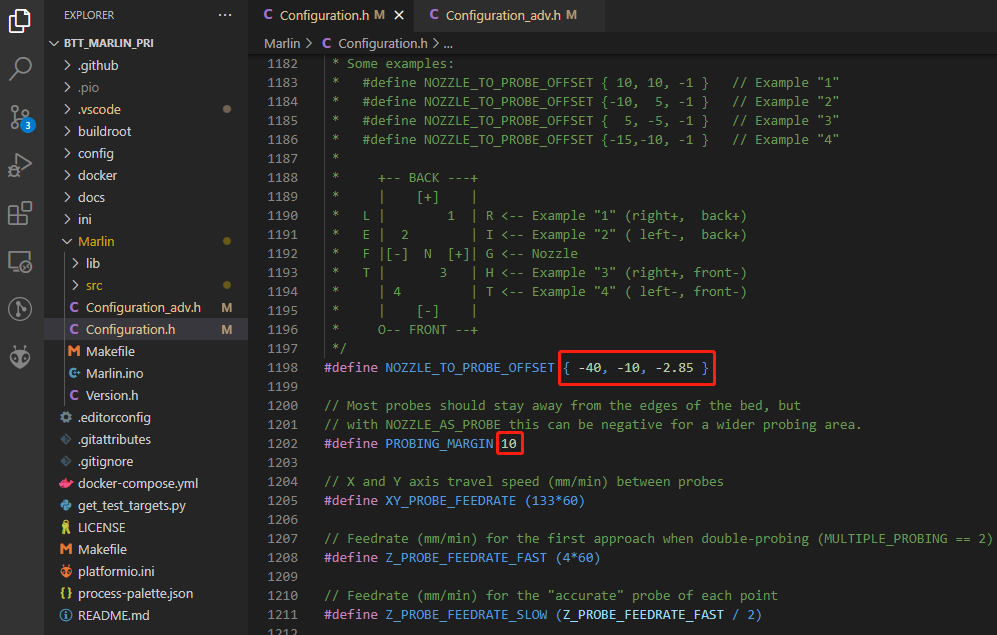
#define NOZZLE_TO_PROBE_OFFSET { -40, -10, -2.85 } // set BLtouch probe offset
#define PROBING_MARGIN 10 // set distance between probe area and print area perimeter
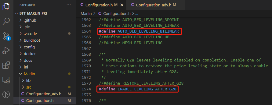
#define AUTO_BED_LEVELING_BILINEAR // set probe pattern
#define RESTORE_LEVELING_AFTER_G28 // apply leveling after G28 homing command
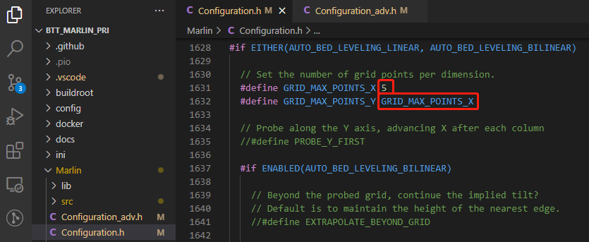
#define GRID_MAX_POINTS_X 5 // set number of probe points for x axis, usually 5 point is sufficient
#define GRID_MAX_POINTS_Y GRID_MAX_POINTS_X // set the number of probe points for Y axis to the same as X axis.
If bltouch also functions as your Z homing sensor, no wiring change is needed, just set it in the firmware.

#define USE_PROBE_FOR_Z_HOMING // use Z Probe(BLtouch) for Z homing
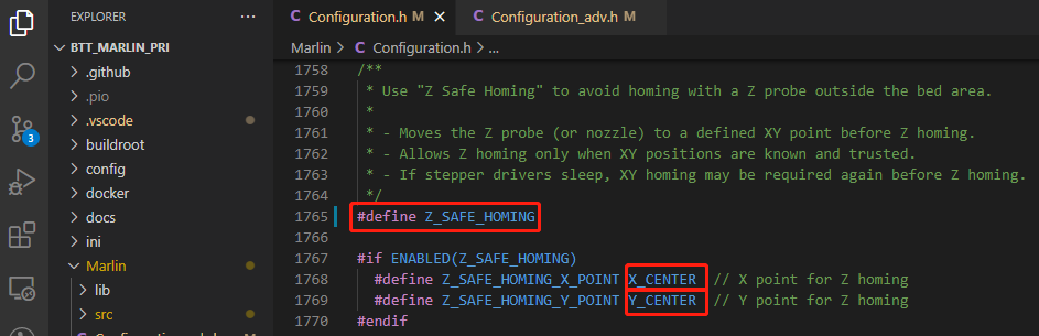
#define Z_SAFE_HOMING // home Z at the center of print bed to prevent probing outside of the print bed.
Auto Power Off(Relay V1.2)
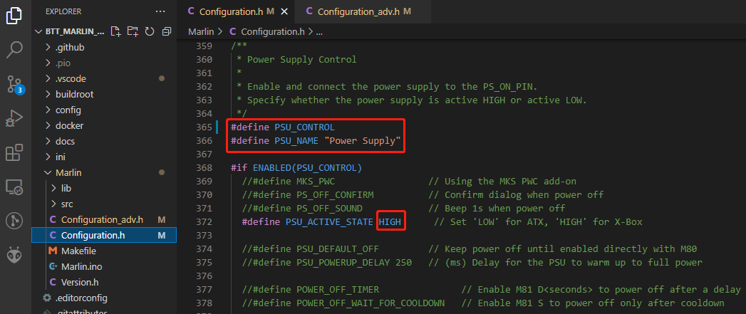
#define PSU_CONTROL // enable PSU control to turn on and off using M80 and M81
#define PSU_ACTIVE_STATE HIGH // set turn on level, Relay V1.2 is turned on with high level and turned off with low level, so this setting needs to be HIGH.
Power Loss Recovery
There are two methods for power loss recovery
1、No extra module needed, the motherboard will write current print status to the SD card after every layer is printed, which shortens the life of the SD card severely.
#define POWER_LOSS_RECOVERY // enable power loss recovery
#define PLR_ENABLED_DEFAULT true // true default to power loss recovery enabled
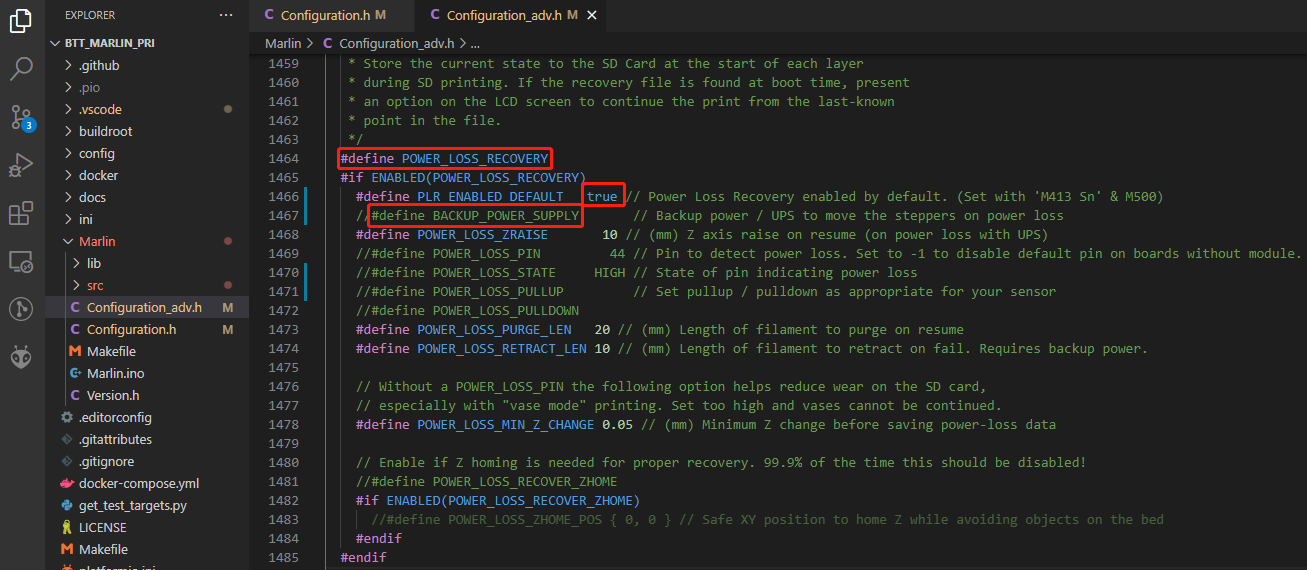
2、External UPS 24V V1.0 module, when power is cut, the module will provide power to the board and signal the board to save current print status to SD card. This method has virtually no effect on the life of the SD card.
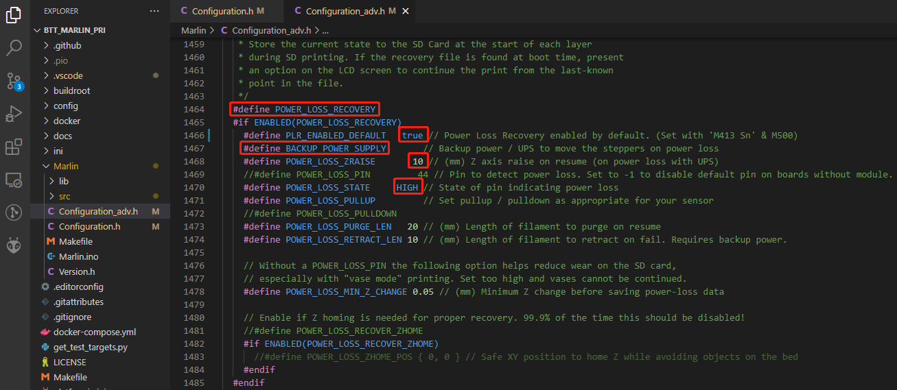
#define POWER_LOSS_RECOVERY // enable power loss recovery
#define PLR_ENABLED_DEFAULT true // true default to power loss recovery enabled
#define POWER_LOSS_ZRAISE 10 // raise the print head by 10mm after power loss to prevent the nozzle from touching the printed part
#define POWER_LOSS_STATE HIGH // set signal level, UPS 24V V1.0 returns low level when not triggered and HIGH level when power is cut, thus this setting needs to be HIGH
RGB
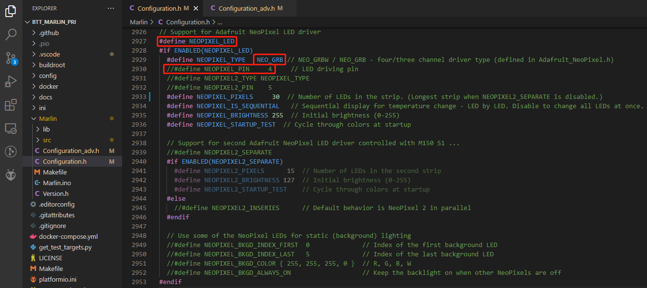
#define NEOPIXEL_LED // enable Neopixel
#define NEOPIXEL_TYPE NEO_GRB // set Neopixel type
//#define NEOPIXEL_PIN 4 // disable PIN setting, use the correct signal pin in the pin file of the motherboard
#define NEOPIXEL_PIXELS 30 // number of LEDs
#define NEOPIXEL_STARTUP_TEST // the light will show red green and blue sequentially to self-test
If you are using displays like LCD2004, 12864, mini12864, etc., you can also control RGB from your display directly.
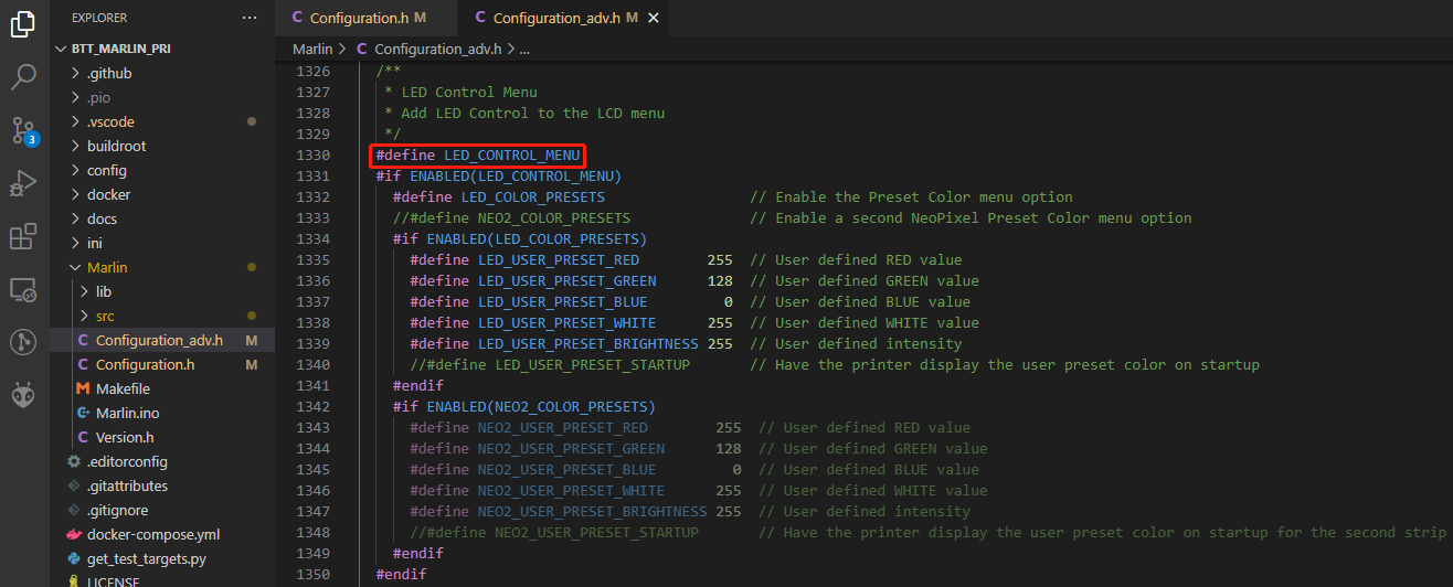
#define LED_CONTROL_MENU // add led control to your menu.
Filament Sensor
Standard filament run out sensors are usually comprised of a microswitch which signals the mainboard of filament status with High or Low level signal.
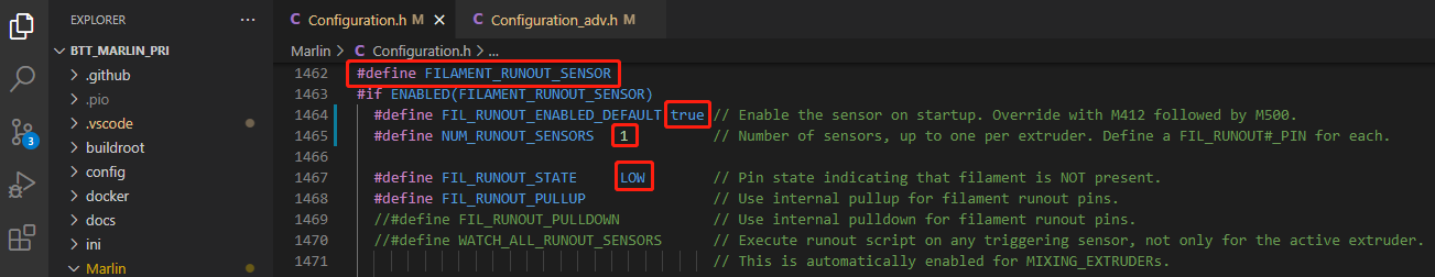
#define FILAMENT_RUNOUT_SENSOR // enable filament run out sensor
#define FIL_RUNOUT_ENABLED_DEFAULT true // true default to filament run out sensor enabled
#define NUM_RUNOUT_SENSORS 1 // number of filament run out sensor
#define FIL_RUNOUT_STATE LOW // voltage level of the filament runout sensor trigger signal. Set according to the actual situation of the module. If the module sends a low level when the filament is abnormal, set it to LOW.
Smart Filament Sensor (SFS V1.0)
The smart filament sensor works by continuously sending signal to the mainboard to communicate filament status.

#define FILAMENT_MOTION_SENSOR // set encoder type
#define FILAMENT_RUNOUT_DISTANCE_MM 7 // set sensitivity, SFS V1.0 nominal setting should be 7mm, which means if no signal of filament movement is detected after 7mm of filament travel command, filament error will be triggered.
The settings below also need to be set to instruct the printer to park the nozzle after filament error is detected.
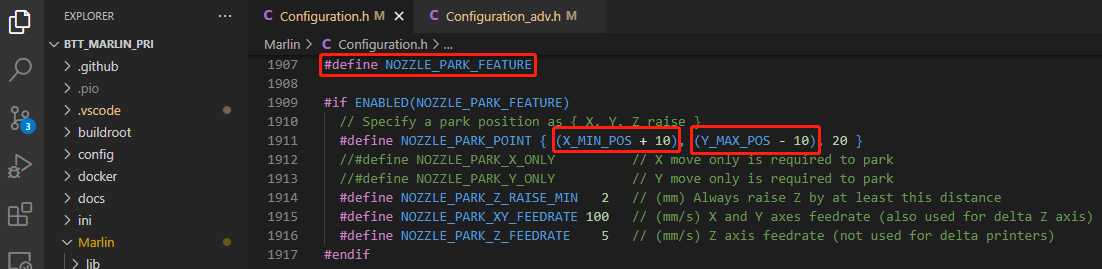
#define NOZZLE_PARK_FEATURE // park nozzle
#define NOZZLE_PARK_POINT { (X_MIN_POS + 10), (Y_MAX_POS - 10), 20 } // set the X, Y and Z offset coordinate of the nozzle
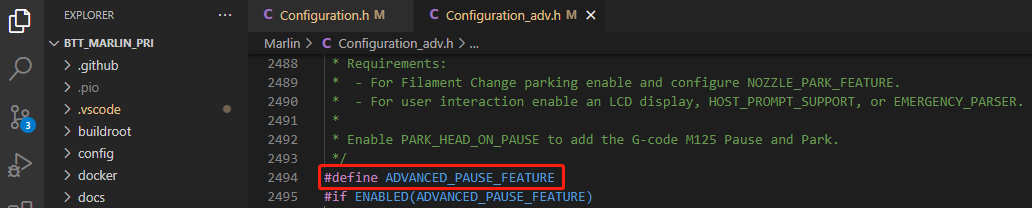
#define ADVANCED_PAUSE_FEATURE // retraction setting of nozzle park movement and filament purge distance after the print is resumed.
ESP3D
The serial port between ESP8266 and Marlin on the motherboard is UART3.
The newest ESP3D firmware can be found at https://github.com/luc-github/ESP3D, compile your own binary file and rename it to "esp3d.bin", copy it to the root directory of the SD card, insert into the motherboard and press the reset button. The bootloader will update the firmware to ESP8266 automatically. If updated successfully, the file will be renamed to "ESP3D.CUR".
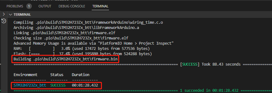
Compile Firmware
1、Click "√" to compile firmware.

2、Copy the compiled "firmware.bin" to SD card and insert to motherboard to update firmware.
Klipper
Preparation
Download OS Image
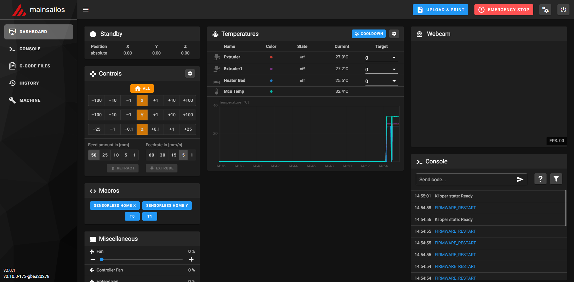
Download your preferred OS image with build-in WebUI, popular choices are Fluidd, Mainsail, etc
Fluidd: https://github.com/fluidd-core/FluiddPI/releases
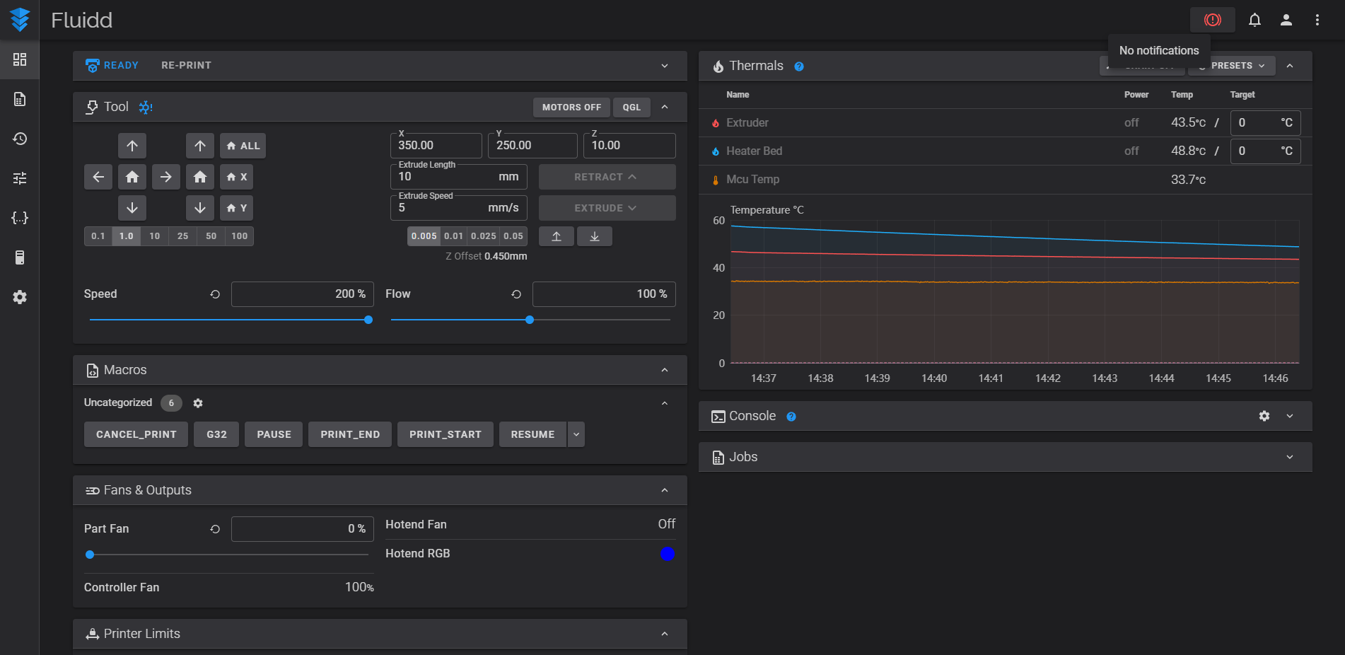
Mainsail: https://github.com/mainsail-crew/MainsailOS/releases
Or refer to Klipper official installation guide using Octoprint.
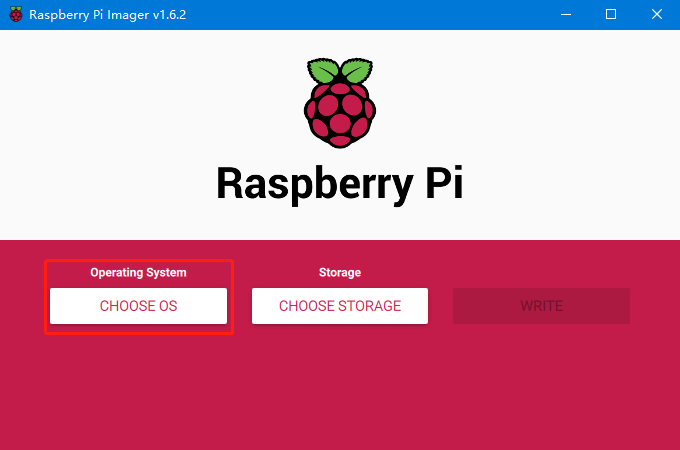
Download and Install Raspberry Pi Imager
Install the official Raspberry Pi Imager https://www.raspberrypi.com/software/
Write Image
1、Insert microSD into your computer via a card reader.
2、Choose OS.
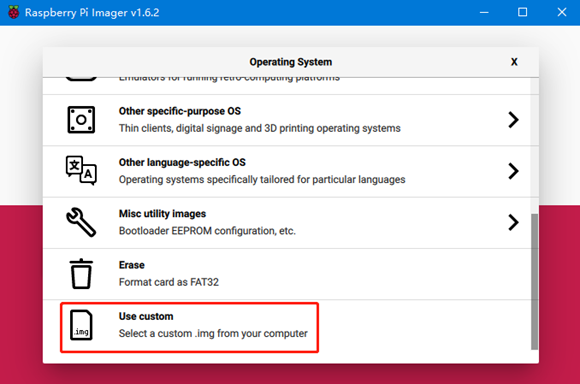
3、Select "Use custom", then select the image that you downloaded.
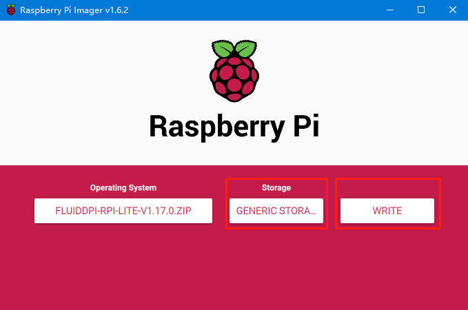
4、Select the microSD card and click "WRITE" (WRITE the image will format the microSD card. Be careful not to select the wrong storage device, otherwise the data will be formatted).
5、Wait for the writing to finish.

WiFi Setting
Note: this step can be skipped if you are using a network cable connection.
1、Reinsert the SD card
2、Find "fluiddpi-wpa-supplicant.txt" or "mainsail-wpa-supplicant.txt" in the SD card root directory, open it with VSCode (do not open it with Windows Notepad)
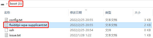
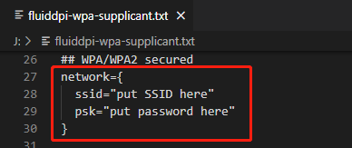
3、Delete "#", insert the correct WiFi SSID and password then save the file.
SSH Connect to Raspberry Pi
1、Install the SSH application Mobaxterm: https://mobaxterm.mobatek.net/download-home-edition.html
2、Insert SD card to Raspberry Pi, wait for system to load after power on, approx. 1-2min.
3、The Raspberry Pi will automatically be assigned an IP address after being successfully connected to the network.
4、Find the Raspberry Pi IP address on your router page.
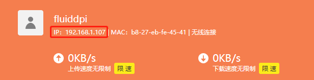
5、Or use the https://angryip.org/ tool, scan all IP addresses in the current network organize by names, and find the IP named Fluidd or Mailsail, as shown below.

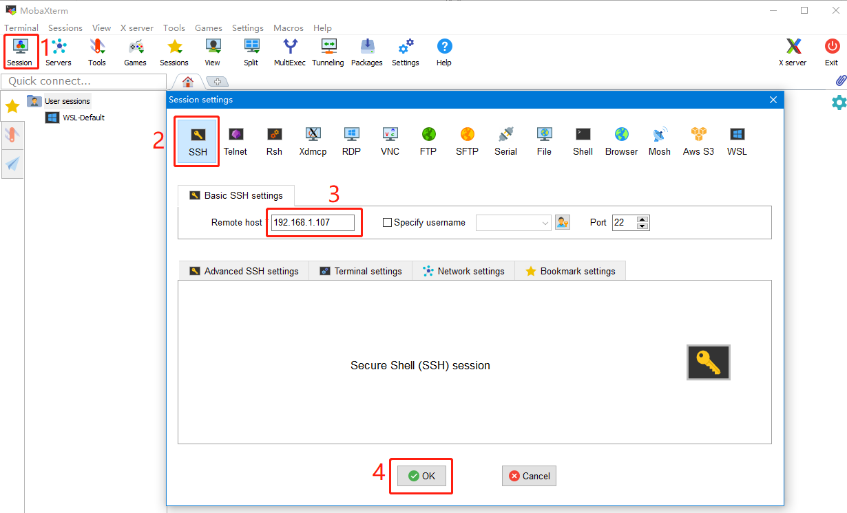
6、Open Mobaxterm and click "Session", and click "SSH", inset the Raspberry Pi IP into Remote host and click "OK" (Note: your computer and the Raspberry Pi needs to be in the same network).
7、Login as: pi password: raspberry
Compile Firmware
1、After SSH successfully connected to the Raspberry Pi, enter in terminal: cd ~/klipper/ make menuconfig Compile with the configuration shown below (if the options below are not available, please update your Klipper source code to the newest version). [*] Enable extra low-level configuration options * Micro-controller Architecture (STMicroelectronics STM32) ---> * Processor model (STM32H723) ---> * Bootloader offset (128KiB bootloader (SKR SE BX v2.0)) ---> * Clock Reference (25 MHz crystal) ---> ** Communication interface (USB (on PA11/PA12)) --->

2、Press q to exit, and Yes when asked to save the configuration.
3、Run make to compile firmware, "klipper.bin" file will be generated in home/pi/klipper/out folder when make is finished, download it onto your computer using the SSH application.

4、Rename klipper.bin to "firmware.bin", copy to SD card to update firmware.
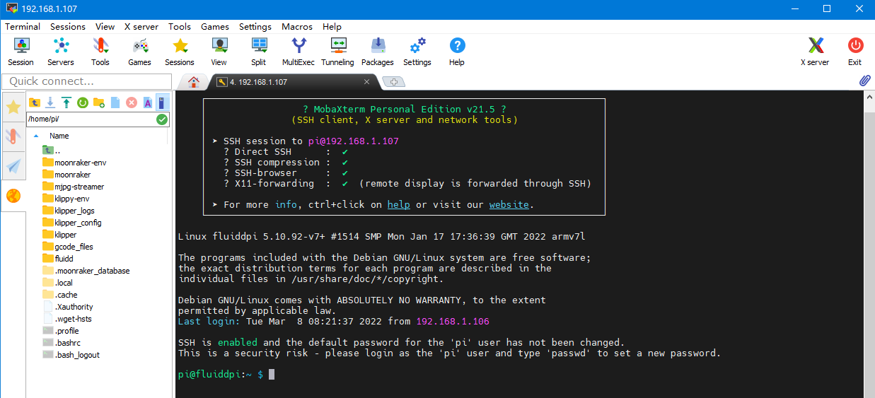
5、Enter: ls /dev/serial/by-id/ in command line to check motherboard ID to confirm whether firmware is updated successfully, as shown below.

copy and save this ID, it is needed when modifying klipper config.
Configure Klipper
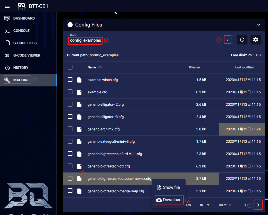
1、Enter your Raspberry Pi IP address into your browser to open the webUI, find the reference config for motherboard in the directory shown below, if there is no such config available, update your Klipper source code to the newest version or download from GitHub:https://github.com/bigtreetech/BIGTREETECH-OCTOPUS-Max-EZ
2、Upload your finished config file into Configuration Files, and rename it to "printer.cfg".
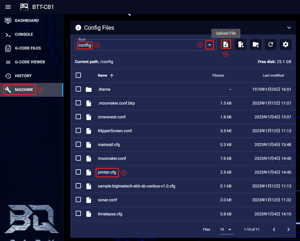
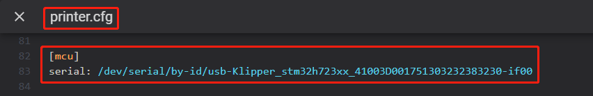
3、Insert the correct motherboard ID.
4、Refer to https://www.klipper3d.org/Overview.html for detailed configuration guide according to your machine type.
Firmware Update
- Make sure microSD is formatted to FAT32.
- Rename your firmware file to "firmware.bin"(note:make sure your system is showing file suffix, if suffix is hided, "firmware.bin" will be shown as "firmware")
- Copy "firmware.bin" to the root directory of your SD card.
- Insert microSD into the motherboard and power on, the bootloader will automatically update the firmware.
- The status indicator LED will flash during the update process.
- When the LED stops flashing and the firmware.bin file has been renamed to FIRMWARE.CUR, the firmware has been successfully updated.
PRECAUTIONS
-
Unplugging and plugging operations should be performed under the condition of power off.
-
Ensure that the voltage selection matches the fan's working voltage to prevent damage.
If you need other resources for this product, please visit https://github.com/bigtreetech/ and find them yourself. If you cannot find the resources you need, you can contact our after-sales support.
If you encounter other problems during use, feel free to contact us, and we are answering them carefully; any good opinions or suggestions on our products are welcome, too and we will consider them carefully. Thank you for choosing BIGTREETECH. Your support means a lot to us!